Electra
The angle between fins should be no less than 90 degrees, for a maximum of four fins. Here, the red fins would radiate heat back onto each other and the white reflectors attempt to prevent this. See discussion below.
RocketCat sez
You might think that the problem with surviving in the "zero degree cold of space" is keeping from freezing to death. Nope, the problem is Heat.
Human bodies are little furnaces, which you can discover if you wrap your limbs and torso in plastic wrap and see how little time it takes to pass out from heat prostration (note to jackasses THIS IS AN ILLUSTRATION, DO NOT ACTUALLY TRY TO DO THIS!). In space, it's not like you can open the window for a cooling breeze, either. Your cosy little habitat module will turn into an oven.
If you stayed awake during Physics 101 class you'll know that the blasted laws of thermodynamics say there are only three ways of getting rid of waste heat. But only one of them will work in space: radiation.
So you'll need heat radiators or the crew is going to die horribly while sweating bullets.
And I am quite sure that you are going to make things infinitely worse by insisting on your precious nuclear power reactors and megawatt laser cannons. Human bodies only make enough waste heat to kill everybody, reactors and lasers can make the entire freaking ship glow white-hot and vaporize.
Ever see those titanic curved towers around nuclear power plants? Yep, cooling towers. You'll need something a bit more high-tech if you do not want your spacecraft's aesthetics spoiled by a 40 meter cooling tower or two.
Laser cannon are much worse. Rick Robinson described them as observatory telescopes with a jet engine at the eyepiece. Ken Burnside said they were blast furnaces that produced coherent light as a byproduct. Whatever you call them they are hot enough to make your ship go from solid directly to Solar-surface hot ionized gas without passing through the molten metal stage first.
But of course heat radiators are one of the major things conspicuous by their absence in science fiction TV shows and movies. Concept artists don't want their ultra-futuristic spacecraft decked with 17th century billowed sails. They even over-ruled Arthur C. Clarke for cryin' out loud! The only exception that comes to mind is the ISV Venture Star from the movie Avatar.
Functionally they are not too different from the radiator on your automobile. Pipes full of radiator fluid are coiled around the cylinder heads and engine block, sucking up the heat so the engine doesn't turn into molten lava. The hot radiator fluid is moved by the coolant pump, carrying the heat into the engine coolant radiator (that flat box on the automobile's nose with all the scalloped holes). In the radiator, the heat is removed from the radiator fluid by conduction with the wind. The cool radiator fluid travels into the engine and the cycle begins anew.
Automobile heat radiator
Actually, in spaceships the heat radiators get rid of heat by … well … radiating, instead of conduction. Different design because there is no wind in space. But you get the idea.
Automobile heat radiator
(needs wind for conduction)
Space Station heat radiators
(uses radiation so it don't need no stinking wind)
ε = emissivity of radiator (theoretical maximum is 1.0 for a perfect black body, real world radiator will be less. Should be at least 0.8 or above to be worth-while)
A = area of radiator (m2)
T = temperature of radiator, this assumes temperature of space is zero degrees (degrees K)
x4 = raise x to the fourth power, i.e, x * x * x * x
My source (Matthew DeBell) says that if P = 150 gigawatts, ε = 0.94, and T = 3000 K, A would be 34,941 m2. Actually it could be half that if you have a two-sided radiator, which would make the radiator 17,470 m2 (a square 132 meters on a side). Which is still freaking huge.
For estimating the mass of the radiator array, go here.
Ken Burnside says that if one examine the equation carefully one will notice that the radiator effectiveness goes up at the fourth power of the heat of the radiator. The higher the temperature, the lower the surface area can be, which lowers the required mass of radiator fins. This is why most radiator designs use liquid sodium or lithium (or things more exotic, still). 1600K radiators mean that you need a lot less mass than 273 K radiators.
Ken Burnside also noted that radiators are large, flimsy, and impossible to armor (except perhaps for the droplet radiator). A liability on a warship. However, Zane Mankowski (author of Children of a Dead Earth) makes a good case that heat radiators can indeed be armored. Mr. Mankowski says the thickness of the radiator material can be increased to provide armor-like protection for the working fluid tubes, with the price of reducing radiator efficiency.
Mr. Burnside has an entire essay about the problem of heat on combat spacecraft, entitled The Hot Equations: Thermodynamics and Military SF. Since thermodynamics is one of the most important (and most neglected in science fiction) factors in combat, the essay will repay careful study.
In the military the old bromide is that amateurs talk about battle tactics while professionals talk about logistics. In the real of spacecraft design, @AsteroidEnergysaid"Amateurs discuss rockets, professionals discuss heat management."
But do realize that if the spacecraft does indeed have a nuclear propulsion system or something else dangerously radioactive,
the radiators must be tapered to keep inside the radiation shadow shield. Or bad things happen.
TWO RADIATOR SYSTEMS NEEDED
I had initially thought that the heat from the life-system could be simply dumped by the same radiator system dealing with the multi-gigawatt waste heat from the propulsion system or power system. Richard Bell pointed out that I had not thought the problem through. Due to the difference in the temperatures of the waste heat from life-system and propulsion, unreasonably large amounts of energy will be required to get the low-level life-system heat into a radiator designed to handle high-level propulsion heat. The bottom line is that there will be two separate radiator systems.
Not only are you going to require two separate radiator systems, the one for the modest cooling required by the life-system is liable to have larger radiator surfaces than the one cooling the multi-gigawatt propulsion system. Radiator effectiveness goes up as the fourth power of the heat of the radiator, remember?
If your spacecraft design includes heat radiators, you recieve Major Diarrhia's Radiator Award. Click for larger image
THERMAL MANAGEMENT IN SPACE
It should be pointed out that in a vacuum environment, convection is no longer available and the only mechanism of rejecting heat is radiation. Radiation follows the Stefan-Boltzmann Law
E = σT4
where
E = the energy rejected
σ = the Stefan-Boltzmann constant, = 5.67 W m-2 K-4
T = the temperature at which the heat is radiated
That is, the total amount of heat radiated is proportional to the surface area of the radiator. And the lower the radiation temperature, the larger the radiator area (and thus the radiator mass, for a given design) must be.
The radiator can only reject heat when the temperature is higher than that of the environment. In space, the optimum radiation efficiency is gained by aiming the radiator at free space. Radiating toward an illuminated surface is less effective, and the radiator must be shielded from direct sunlight.
The rejection of heat at low temperatures, such as would be the case in environmental control and in the thermal management of a materials processing unit, is particularly difficult.
Space-Based Power Generating Systems
Solar photovoltaic systems have a generating capability of up to several hundred kilowatts. The power output range of solar thermal systems is expected to be one hundred to perhaps several hundred kilowatts. While in principle these power systems can be expanded into the megawatt region, the prohibitive demands for collection area and lift capacity would appear to rule out such expansion. Megawatt and multimegawatt nuclear power reactors adapted for the space environment appear to offer a logical alternative.
Solar photovoltaics themselves will not burden the power generating system with a direct heat rejection requirement, since the low energy density of the system requires such a great collection area that it allows rejection of waste radiant energy. However, if these systems are to be employed in low Earth orbit or on a nonterrestrial surface, then a large amount of energy storage equipment will be required to ensure a continuous supply of power (as the devices do not collect energy at night). And the round-trip inefficiencies of even the best energy storage system today will require that a large fraction—perhaps 25 percent—of the electrical power generated must be dissipated as waste heat and at low temperatures.
Solar thermal systems, which include a solar concentrator and a dynamic energy conversion system, are presumed to operate at relatively high temperatures (between 1000 and 2000 K). The efficiencies of the energy conversion system will lie in the range of 15 to perhaps 30 percent. Therefore we must consider rejecting between 70 and 85 percent of the energy collected. In general, the lower the thermal efficiency, the higher the rejection temperature and the smaller the radiating area required. As with solar photovoltaic systems, the inefficiencies of the energy storage system will have to be faced by the heat rejection system, unless high temperature thermal storage is elected.
The current concepts for nuclear power generating systems involve reactors working with relatively low-efficiency energy conversion systems which reject virtually all of the usable heat of the reactor but at a relatively high temperature. Despite the burdens that this low efficiency places on nuclear fuel use, the energy density of nuclear systems is so high that the fuel use factor is not expected to be significant.
In all of these systems the output power used by the production system in environmental control and manufacturing (except for a small fraction which might be stored as endothermic heat in the manufactured product) will have to be rejected at temperatures approaching 300 K.
As an example of the severity of this problem, let us examine the case of a simple nuclear power plant whose energy conversion efficiency from thermal to electric is approximately 10 percent. The plant is to generate 100 kW of useful electricity. The reactor operates at approximately 800 K, and a radiator with emissivity equal to 0.85 would weigh about 10 kg/m2. The thermal power to be dissipated from the reactor would be about 1 MW. From the Stefan Boltzmann Law, the area of the radiator would be about 50 m2 and the mass approximately 500 kg. This seems quite reasonable.
However, we must assume that the electricity generated by the power plant, which goes into life support systems and small-scale manufacturing, would eventually have to be dissipated also, but at a much lower temperature (around 300 K). Assuming an even better, aluminum radiator of about 5 kg/m2, with again an emissivity of 0.85, in this case we find that the area of the low temperature heat rejection component is 256 m2, with a mass approaching 1300 kg.
Using the Stefan-Boltzmann Law,
E1 = 5.67×10⁻⁸ W m-2 K-4 (800 K)4
E1 = 5.67×10⁻⁸ W m-2 K-4 × 4096×108 K4
E1 = 5.67 W m-2 × 4.10×103
E1 = 23.3 kW m-2
E2 = 5.67×10⁻⁸ W m-2 K-4 (300 K)4
E2 = 5.67×10⁻⁸ W m-2 K-4 × 81×108 K4
E2 = 5.67 W m-2 × 81
E2 = 459 W m-2
100 kW / 459 W m-2 = 0.2179×10³ m2 = 218 m2
and 218 m2 / 0.85 = 256 m2
Therefore, we can see that the dominant heat rejection problem is not that of the primary power plant but that of the energy that is used in life support and manufacturing, which must be rejected at low temperatures. Using the waste heat from the nuclear power plant for processing may be effective. But, ironically, doing so will in turn require more radiator surface to radiate the lower temperature waste heat.
Heat Rejection Systems
In this section I will deal with systems designed to meet the heat rejection requirements of power generation and utilization. These heat rejection systems may be broadly classified as passive or active, armored or unarmored. Each is expected to play a role in future space systems.
Fig. 36: Components and Principle of Operation of a Conventional Heat Pipe
A conventional heat pipe consists of a sealed container with a working fluid, a passageway for vapor, and a capillary wick for liquid transport. During operation, the heat pipe is exposed to external heat at one end (the evaporator section). This heat causes the working fluid in the capillary wick to vaporize, removing heat equal to the heat of vaporization of the fluid. The vapor is forced down the center of the pipe by pressure from the newly forming vapor. When the vapor reaches the cool end of the pipe (the condenser section), it condenses to a liquid. The liquid soaks into the capillary wick, through which it travels back to the evaporator section. As the fluid condenses, it gives up the heat of vaporization, which is then conducted outside the end of the pipe.
Heat pipes: The first of these, called the “heat pipe,” is conventionally considered the base system against which all others are judged. It has the significant advantage of being completely passive, with no moving parts, which makes it exceptionally suitable for use in the space environment.
For the convenience of the reader, I will briefly describe the operational mechanism of the basic heat pipe. (See figure 36.) The heat pipe is a thin, hollow tube filled with a fluid specific to the temperature range at which it is to operate. At the hot end, the fluid is in the vapor phase and attempts to fill the tube, passing through the tube toward the cold end, where it gradually condenses into the liquid phase. The walls of the tube, or appropriate channels grooved into the tube, are filled with a wick-like material which returns the fluid by surface tension to the hot end, where it is revaporized and recirculated.
Essentially the system is a small vapor cycle which uses the temperature difference between the hot and cold ends of the tube as a pump to transport heat, taking full advantage of the heat of vaporization of the particular fluid.
The fluid must be carefully selected to match the temperature range of operation. For example, at very high temperatures a metallic substance with a relatively high vaporization temperature, such as sodium or potassium, may be used. However, this choice puts a constraint on the low temperature end since, if the fluid freezes into a solid at the low temperature end, operation would cease until the relatively inefficient conduction of heat along the walls could melt it. At low temperatures a fluid with a low vaporization temperature, such as ammonia, might well be used, with similar constraints. The temperature may not be so high as to dissociate the ammonia at the hot end or so low as to freeze the ammonia at the cold end.
With proper design, heat pipes are an appropriate and convenient tool for thermal management in space systems. For example, at modest temperatures, the heat pipe could be made of aluminum, because of its relatively low density and high strength. Fins could be added to the heat pipe to increase its heat dissipation area. The aluminum, in order to be useful, must be thin enough to reduce the mass carried into space yet thick enough to offer reasonable resistance to meteoroid strikes.
A very carefully designed solid surface radiator made out of aluminum has the following capabilities in principle: The mass is approximately 5 kg/m2 with an emissivity of 0.85; the usable temperature range is limited by the softening point of aluminum (about 700 K). At higher temperatures, where refractory metals are needed, it would be necessary to multiply the mass of the radiator per square meter by at least a factor of 3. Nevertheless, from 700 K up to perhaps 900 K, the heat pipe radiator is still a very efficient method of rejecting heat.
A further advantage is that each heat pipe unit is a self-contained machine. Thus, the puncture of one unit does not constitute a single-point failure that would affect the performance of the whole system. Failures tend to be slow and graceful, provided sufficient redundancy.
Fig. 37: Pump Loop Radiators on the Space Shuttle Payload Bay Doors
a. The space radiators, which consist of two deployable and two fixed panels on each payload bay door, are designed to reject waste heat during ascent (doors closed) and in orbit (doors open). Each panel contains parallel tubes through which the Freon in the heat loops can pass, bringing waste heat from other parts of the orbiter. The total length of Freon tubing in these panels is 1.5 km.
Pump Loop Radiators on the Space Shuttle Payload Bay Doors
b. The panels have a heat rejection capacity of 5480 kJ/hr (5400 Btu/hr) during ascent through the atmosphere with the doors closed and 23 kJ/hr (21.5 Btu/hr) during orbital operations with the doors open.
Pump loop system: The pump loop system has many of the same advantages and is bounded by many of the same limitations associated with the heat pipe radiator. Here heat is collected through a system of fluid loops and pumped into a radiator system similar to conventional radiators used on Earth. It should be pointed out that in the Earth environment the radiator actually radiates very little heat; it is designed to convect its heat. The best known examples of the pump loop system currently used in space are the heat rejection radiators used in the Shuttle. These are the inner structure of the clamshell doors which are deployed when the doors are opened (fig. 37).
Pump loop systems have a unique advantage in that the thermal control system can easily be integrated into a spacecraft or space factory. The heat is picked up by conventional heat exchangers within the spacecraft, the carrier fluid is pumped through a complex system of pipes (extended by fins when deemed effective), and finally the carrier is returned in liquid phase through the spacecraft. In the case of the Shuttle, where the missions are short, additional thermal control is obtained by deliberately dumping fluid.
Since the system is designed to operate at low temperatures, a low density fluid, such as ammonia, may on occasion, depending on heat loading, undergo a phase change. Boiling heat transfer in a low gravity environment is a complex phenomenon, which is not well understood at the present time. Because the system is subjected to meteoroid impact, the basic primary pump loops must be strongly protected.
Despite these drawbacks, pump loop systems will probably be used in conjunction with heat pipe systems as thermal control engineers create a viable space environment. These armored (closed) systems are rather highly developed and amenable to engineering analysis. They have already found application on Earth and in space. A strong technology base has been built up, and there exists a rich literature for the scientist-engineer to draw on in deriving new concepts.
Advanced Radiator Concepts
The very nature of the problems just discussed has led to increased efforts on the part of the thermal management community to examine innovative approaches which offer the potential of increased performance and, in many cases, relative invulnerability to meteoroid strikes. Although I cannot discuss all of these new approaches, I will briefly describe some of the approaches under study as examples of the direction of current thinking.
Improved conventional approaches: The continuing search for ways to improve the performance of heat pipes has already shown that significant improvements in the heat pumping capacity of the heat pipe can be made by clever modifications to the return wick loop. Looking further downline at the problem of deployability, people are exploring flexible heat pipes and using innovative thinking. For example, a recent design has the heat pipes collapsing into a sheet as they are rolled up, the same way a toothpaste tube does. Thus, the whole ensemble may be rolled up into a relatively tight bundle for storing and deploying. However, because the thin-walled pipes are relatively fragile and easily punctured by meteoroids, more redundancy must be provided. The same principles, of course, can be applied to a pump loop system and may be of particular importance when storage limits must be considered. These are only examples of the various approaches taken, and we may confidently expect a steady improvement in the capability of conventional thermal management systems.
Fig. 38: Two Concepts for a Liquid Droplet Radiator
In one concept, droplets are generated at the base of a cone which contains the source of the waste heat (a nuclear reactor, for example), and the molten droplets are sprayed to a six- armed collector array, where they are caught and then pumped back through a central pipe to the reactor.
Two Concepts for a Liquid Droplet Radiator
In a somewhat similar concept (bottom), a deployable boom has the droplet generator at one end and the droplet collector at the other, with a fluid feed line between. Here the droplets are sprayed in a single planar pattern.
The liquid droplet radiator: The basic concept of the liquid droplet radiator is to replace a solid surface radiator by a controlled stream of droplets. The droplets are sprayed across a region in which they radiate their heat; then they are recycled to the hotter part of the system. (See figure 38.)
It was demonstrated some time ago that liquid droplets with very small diameters (about 100 micrometers) are easily manufactured and offer a power-to-mass advantage over solid surface radiators of between 10 and 100. In effect, large, very thin radiator sheets can be produced by the proper dispersion of the droplets. This system offers the potential of being developed into an ultralightweight radiator that, since the liquid can be stored in bulk, is also very compact.
The potential advantages of the liquid droplet radiator can be seen if we consider again the problem that was discussed at the end of the section on heat pipe radiators. We found that a very good aluminum radiator would require 256 m2 and have a mass of nearly 1300 kg to radiate the low temperature waste heat from lunar processing. Using the properties of a liquid droplet radiator and a low density, low vapor pressure fluid such as Dow-Corning 705, a common vacuum oil, we find that, for the same area (which implies the same emissivity), the mass of the radiating fluid is only 24 kg.
Even allowing a factor of 4 for the ancillary equipment required to operate this system, the mass of the radiator is still less than 100 kg.
To achieve efficiency, the designer is required to frame the radiator in a lightweight deployable structure and to provide a means of aiming the droplets precisely so that they can be captured and returned to the system. However, present indications are that the droplet accuracies required (milliradians) are easily met by available technology. Recently, successful droplet capture in simulated 0 g conditions has been adequately demonstrated. An advantage of a liquid droplet radiator is that even a relatively large sheet of such droplets is essentially invulnerable to micrometeoroids, since a striking micrometeoroid can remove at most only a few drops.
The reader may be concerned that the very large surface area of the liquid will lead to immediate evaporation. However, liquids have recently been found that in the range of 300 to 900 K have a vapor pressure so low that the evaporation loss during the normal lifetime of a space system (possibly as long as 30 years) will be only a small fraction of the total mass of the radiator.
Thus, the liquid droplet radiator appears promising, particularly as a low temperature system where a large radiator is required.
Liquid droplet radiators for applications other than 0 g have been suggested. For example, in the lunar environment fluids with low vapor pressures can be used effectively as large area heat dissipation systems for relatively large-scale power plants. We may well imagine that such a system will take on the appearance of a decorative fountain, in which the fluid is sprayed upward and outward to cover as large an area as possible. It would be collected by a simple pool beneath and returned to the system. Such a system would be of particular advantage in the lunar environment if low mass, low vapor pressure fluids could be obtained from indigenous materials. Droplet control and aiming would no longer be as critical as in the space environment; however, the system would need to be shaded from the Sun when it is in operation.
While this system is far less developed than the systems previously discussed, its promise is so high that it warrants serious consideration for future use, particularly in response to our growing needs for improved power management.
Fig. 39: Belt Radiator
A related heat rejection technology is the belt radiator concept. Here the liquid is present as a thin coating on two rotating belts. As the belts rotate through the drive mechanism, they pick up hot fluid from the heat exchanger. Then, as the belts rotate through space, the fluid loses its heat. This system does not have the advantage of the high surface-area- to-mass ratio possible with a liquid droplet radiator, but it still may offer superior properties of heat transfer and damage resistance compared to solid radiators.
Belt radiator concepts: The belt radiator concept is a modification of the liquid droplet concept in which an ultrathin solid surface is coated with a very low vapor pressure liquid (see fig. 39). While the surface-to-volume ratio is not limited in the same fashion as for a cylindrical heat pipe, it does not quite match that of the liquid droplet radiator. However, this system avoids the problem of droplet capture by carrying the liquid along a continuous belt by surface tension. The liquid plays a double role in this system by acting not only as the radiator but also as the thermal contact which picks up the heat directly from a heat transfer drum. Variations on this scheme, in which the belt is replaced by a thin rotating disk, are also feasible but have yet to be fully assessed.
High-powered weapons need heat radiators as well
Or it's "How About A Little Fire, Scarecrow?" time artwork by 反骨max
Multiple Radiator Panels
If the spacecraft has one heat radiator plate, you do not have to worry about waste heat radiated from one plate shining on a second plate. Such shine is counter-productive, shined heat is re-absorbed by the second plate which is not helping matters.
However, a single plate has no redundancy. One meteor hole and the plate could be rendered in operative, forcing a shut-down of the nuclear reactor or whatever. Or one hole from hostile weapons fire, for that matter.
The simplest solution is two heat radiator plates that are oriented coplanar, mounted on opposite sides of the spacecraft. Since they are coplanar it is impossible for them to shine on each other. You can have as many coplanar heat radiators as you want, but this tends to force the spacecraft to be elongated. This increases the spacecraft's moment of inertia, so it turns more slowly.
If you want more than two radiators without a dachshund shaped ship, you will be forced to have radiators that are not coplanar. The heat shine penalty goes up with each extra radiator panel added.
MULTIPLE RADIATOR PANELS
Electra
The upper two-plate ship is pretty optimal, with two plates emitting 2.0 plates worth of heat (100% efficiency).
If the four-plate ship below had no reflectors, you would have four plates emitting 2.8 plates worth of heat (71% efficiency).
Reflectors attempt to prevent the radiators from shining on each other to increase the efficiency
You noted that
having too many radiators distributed about an axis causes them to
radiate into each other. It all boils down to what's known as a face factor, essentially how
much of the radiation released by a surface is intercepted by another
one. For two plates of equal length separated by an angle alpha (α), the
face factor is:
F = 1 - sin(α/2)
So you can see right off the bat that for 2 radiators opposite each
other, α = 180°, α/2 = 90° and the face factor is 0, no interception.
But go up:
Multiple Radiator Panels
#
Face Factor
Emit
Efficiency
1
0.000000000
1.00000000
1.000000000
2
0.000000000
2.00000000
1.000000000
3
0.133974596
2.598076211
0.866025404
4
0.292893219
2.828427125
0.707106781
5
0.412214748
2.938926261
0.587785252
6
0.500000000
3.000000000
0.500000000
7
0.566116261
3.037186174
0.433883739
8
0.617316568
3.061467459
0.382683432
9
0.657979857
3.078181290
0.342020143
10
0.690983006
3.090169944
0.309016994
11
0.718267443
3.099058125
0.281732557
12
0.741180955
3.105828541
0.258819045
# number of radiators spaced around the ship's long axis
Face Factor how much heat radiation from a radiator is wastefully intercepted by another radiator
Emit how much heat is effectively radiated by the total radiator array, in units of single radiator panels
Efficiency how efficient is this array at getting rid of heat, single panel = 1.00 or 100%
The second column is face factor, the third column is how much is
emitted relative to a single surface, and the last is "efficiency",
how much every individual panel is emitting relative to a single
unlimited surface (efficiency is just 1 - F = sin(α/2), which is
itself the face factor for the surface relative to its unobstructed
surroundings). As you can see, it falls off very very quickly; the
third radiator is only 60% as effective (goes up from 2.00 to 2.60), and the fourth adds to this
only marginally (goes up from 2.60 to 2.80). Unless there really isn't room to simply stretch out
the panels, it just doesn't seem worth it to pack more than 3 about an
axis, and even 3 might be a stretch.
Neat thing is, using the face factor you can figure out the efficiency
of radiators in weird geometries. My textbook has face factors for
cylinders, enclosed spaces and plates of unequal size, if you so
desire, which is to say I could tell you how much is going into your
spaceship, or out an open dock.
Another neat side effect of face factors is that you can make a
radiator more efficient per given mass by poking holes right through
it, since the inner surface of the hole radiates at least partly out
into its surroundings (the rest radiates back into itself, but that
isn't really a problem). This reduces efficiency per unit area (though
interestingly not by much for giant holes), and the panel is
significantly weaker as a result (even more than you'd think, since
the hole provides an area of stress concentration — it can reach
multiples what it would normally there), but for very small holes that
are very close together, you can get efficiencies per mass that are
many times higher than they would be for a straight panel.
Take this arrangement: a square grid of side L, with a hole in the
center of each square and one on each vertex, each hole being of
radius 0.35L so that the holes at the vertices are nearly touching
that in the middle. Say, for L varying from 0.1 to 1, 10 and 100 times
thickness, relative mass efficiency goes up 4.342, 4.010, 1.828 and 1.094 times(by the way, because the relative size of the hole is the same, you need 4.660 times the area of panelling to get the same mass
as a continuous radiator).
(ed note: the above was orginally erroneously writen as 1.199, 2.204, 4.184 and 4.609 times)
You can force even more holes into there if they're arranged
hexagonally; take a hexagon of side L, with a hole at the center and
one each vertex, you can reach a radius of up to 0.5L. Now, for L
varying again from 0.1 to 1, 10 and 100 times the thickness, relative
mass efficiency goes up 10.741, 9.610, 2.763 and 1.193 times over (in
this case, you need 10.74 times the area of panelling to get the same
mass as a continuous radiator)!
(ed note: the above was orginally erroneously writen as 1.486, 5.035, 9.816 and 10.644 times)
Given that "every gram counts", it's almost certainly worth the
fragility. You could probably thicken the panels somewhat to make up
for it and hit a sweetspot
From Zach Hajj (aka Zerraspace) (2015)
MULTIPLE RADIATOR PANELS 2
For one, I hoped to clarify some things in my former post, so I've
provided images for the hole arrangements to make them easier to
understand.
It turns out I made a little slip with the calculation —
it's smaller holes that are close together that give higher
efficiency, not large holes. It just means correcting a couple of
sentences there — "very small" rather than "very large" holes, and for
the figures, for a square grid: for L varying from 0.1 to 1, 10 and
100 times thickness, relative mass efficiency goes up 4.342, 4.010,
1.828 and 1.094 times,
and for a hexagonal grid: for L varying from
0.1 to 1, 10 and 100 times thickness, relative mass efficiency goes up
10.741, 9.610, 2.763 and 1.193 times.
(ed note: I tried to make the changes specified in the above paragraph in the prior quote "Multiple Radiator Panels". They are marked in bold red letters.)
Now, for the new stuff. I’ve found out there’s a hard limit to the
emission you can get by stuffing more panels about an axis. You see,
mathematically, sine can be expressed by a Taylor series, so broken
down:
E = n sin(a/2)
= n sin(2π/2n)
= n sin(π/n)
= n ((π/n) - (π/n)3/3! + (π/n)5/5! - (π/n)7/7!+…))
= π (1-(π/n)2/3! + (π/n)4/5! - (π/n)6/7!+…)
As n grows, π/n shrinks, till all terms but the first disappear,
leaving us with π! You can think about this in geometric terms too —
emission is basically the perimeter of the shape formed by the joining
of the tips of each plate, so as n gets really huge, the shape
transforms into a circle (in fact, this is how computers build
circles, as n-gons with huge values of n). Instead of working to pump
out every last drop possible within a confined space by throwing in
essentially useless panels, you could replace them with one large
cylindrical panel, giving you π emission, the maximum possible, but
with 100% efficiency because there’s no self-interception! That being
said, you’ll still lose out to two panels on opposite sides of the
ship, seeing as those can get double the emission by radiating from
both sides.
But don’t discount those extra panels yet. See, the formula I gave you
makes one critical assumption — that the length of the plate so
greatly outstrips width it might as well be infinite. This is not
necessarily the case, so I decided to go and find a more expressive
formula, here - http://www.thermalradiation.net/sectionc/C-16.html .
It involves a very complex integral, so using a MATLAB code, I managed
to solve it numerically, cross-referencing with the values given on
the website to ensure accuracy. The results are presented in the
attached Excel file; the values are only somewhat higher for
triangular plates.
It seems that for small aspect ratios (width/length is less than ¼ or
so), the value of the face factor is closely approximated by the
simplistic formula I gave earlier. However, it falls off dramatically
as the aspect ratio climbs, and for very large values (above 50 or
so), the other panels barely present any obstruction at all!
The reason for this is that emission isn’t all perpendicular from the
radiating surface — that’s simply the direction in which it is most
intense. Some is emitted at an angle, so for huge aspect ratios, more
can escape through the open sides. This is what makes belt radiators
and heat pipes so effective, and lets us get any performance
improvement out of poking holes in the panels. It also allows you to
experiment with novel designs, as you can now have radiators that
point right at each other without adjacent surfaces being rendered
completely useless, so long as there’s some distance between them.
For one, you can further reduce face factor by swapping out flat
panels. Cylindrical radiators fare spectacularly well: if my code is
on the money, for length/radius greater than or equal to 5, face
factor for up to 12 such tubes arranged radially is 2.45% or less,
essentially negligible, and while I could not find a formula for
cones, I can tell you performance will be intermediate between flat
plats and cylinders. Attack Vector: Tactical’s radiator spikes would
seem to be in the realm of possibility, though I wouldn’t vouch for
their exact arrangement given in the illustrations (arranging spikes
to the front and rear of one another blocks more and more of their
surroundings, which kind of defeats the purpose of using them).
(Images for rectangular and circular panels are from Fundamentals of
Mass and Heat Transfer, 6th Edition, by Frank Incropera, David Dewitt,
Theodore Bergman and Adrienne Lavine; the last is from the online
Catalog of Radiation Heat Transfer Configuration Factors, by John R.
Howell at the University of Texas in Austin, available here:
http://www.thermalradiation.net/tablecon.html )
Take two square panels of side X, separated by the same distance
(X/L=1), then the face factor is only 0.2, not exactly murderous; you
get nearly the same value if the panels are triangular (theta = 45,
c/b = 1) or circular, with diameter equal to the separating distance
(rj/L=0.5, L/ri = 2). If one dimension of a rectangular panel is much
shorter than the distance between them, say a fifth of it or less
(either X/L or Y/L < 0.2), then it doesn’t matter what the other
dimension is, face factor is always below 0.1, and the same can be
said for triangles. You could get some interesting geometries out of
this — a homage to the TIE fighter, anyone?
Again, this analysis has to be taken with a grain of salt. None of
these is a free lunch. You have to transport heat across that distance
of paneling without temperature dropping off too much, or you’re only
going to get the real heat disposal near the body of the craft, which
just so happens to be where most of the interception takes place. This
isn’t a problem when your panels are only a couple or even tens of
meters across, but it does become a concern when they stretch
kilometers away from the ship body. Moreover, they require more mass
in the form of additional support and shadow shield coverage (if the
ship needs such), and they present an even greater target for weapons’
fire. Whether or not this always pays off is a valid question.
From Zach Hajj (aka Zerraspace) (2015)
Open-Cycle Cooling
With certain kinds of rocket engines, you can cheat and avoid the need for heat radiators (and their ugly penalty weight). The dodge is called "open-cycle cooling", where the waste heat is carried away by the exhaust plume. In effect, the exhaust is their radiator, made out of rocket plasma instead of metal. And since the exhaust is not physically connected to the spacecraft, the "radiator" adds zero mass to the rocket structure.
But it only works on certain kinds of engines. And it doesn't work at all to cool most spacecraft weapons, with the exception of weird weapons like open-cycle chemical and bomb-pumped lasers.
Since the heat is carried by the rocket exhaust, you need plenty of exhaust. Which means each second of exhaust needs lots of propellant. Which means the engine needs a large propellant mass flow(called "ṁ" or "mdot"). This has consequences: raising the mdot will raise the thrust, but will also drastically lower the exhaust velocity and specific impulse. Basically the engine will accelerate the spacecraft more quickly, but the gas mileage will fall into the toilet.
Some rocket engines (such as ion drives) have large exhaust velocities but low thrust. They cannot use open-cycle cooling because their ain't enough propellant in the exhaust plume to carry away all the heat.
Other engines (such as solid-core nuclear thermal rockets) have relatively low exhaust velocities but high thrust. They work splendidly with open-cycle cooling. So as a general rule, most NERVA type engines do not have heat radiators. If they do, this is because they are bimodal NTRs, and the radiator is only used when there is no rocket exhaust (when it is generating electricity instead of thrust).
The Glow
BLACKBODY COLOR BY TEMPERATURE IN KELVIN (log scale)
click for larger image
What color will the radiators glow? A practical one will only glow dull red. You can use the Blackbody Spectrum Viewer to see what temperature corresponds to what color. If it was glowing white hot, the temperature would be around 6000 Kelvin. This would be difficult for a solid radiator, since even diamond melts at 4300 degrees K.
Note that the blackbody spectrum does NOT go up the rainbow. Both go from red to orange to yellow. But the rainbow continues to green, blue, indigo, and violet. The blackbody spectrum instead continues to white, blueish-white, and light blue.
The force fields in E. E. "Doc" Smith's Skylark & Lensman series and the Langston Field in Larry Niven & Jerry Pournelle's The Mote in God's Eye go up the rainbow spectrum as enemy energy beams assault them. But that's space opera, not reality.
In the diagram above the blackbody spectrum is the curved black line labeled "Planckian Locus". Which as you can see passes through red, orange, yellow, white, blueish-white, and light blue. But it never gets close to green at all. Nor purple or magenta either.
This is also why there ain't no such thing as a green star.
Black body curves of Planck for various temperatures
Why does this happen? Well, mostly because the human eye is a most imperfect optical instrument.
A blackbody emission that has its peak in the green part of the rainbow spectrum is also emitting lots of light in the red and blue parts of the spectrum (note how the curves are not sharp peaks but rather sloping curves). To the human eye a mix of green, blue, and red light looks like white.
Above 16,000 K or so all stars look the same shade of blue. In reality the relative intensities of the shorter frequencies are quite different at various temperatures, but to the imperfect human eye they all look like blue. A spectroscope can see the differences quite easily.
The fact that the human eye can be fooled this way is the reason why computer monitors have pixels for red, green, and blue; but no pixels for yellow, orange, or violet. Since the imperfect human eye sees a mix of red and green light as yellow, why go to the expense of adding yellow pixels?
Optimum Radiator Temperature
Here is some scary math about radiators from Dr. Tony Valle and Ray Robinson, along with some interesting conclusion. Remember that according to the radiator equation the hotter temperature the radiator is run at, the more waste heat it can dispose of.
RocketCat sez
Their "interesting conclusion" is that ya don't wanna design your heat radiator to run at 100% efficiency or the blasted thing will be huge, unwieldy, and bloated with penalty mass. Remember every gram counts!
For the sweet spot between maximum efficiency and minimum mass, design the radiator temperature to run at 3/4 of the temperature of the power plant's hot end. But if you don't wanna take my word for it, feel free to dive into the following scary math.
OPTIMAL COLD / HOT RATIO = 0.75
It is surprising but there is an optimum temperature ratio at which to run a starship heat exchanger (or similar power source) to achieve maximum free power with a minimum of radiator area. The only assumptions necesary are that the power source obeys the laws of thermodynamics and that the starship may only get rid of waste heat by radiating.
Let us assume that we have a heat engine as a power source with a relative efficiency of η, and an absolute efficiency is η times the Carnot efficiencyε. We can write the available free power, F, as:
F = Qηε = Qη(1 - T1/T2)
where Q is the rate of heat flow into the exchanger and T1 and T2 are the temperatures of the cold and hot sides of the engine, respectively. The waste heat, H, released into the starship is Q - F, or:
H = Q(1 - η + ηT1/T2) H = F (1 - η + ηT1/T2)/η(1 - T1/T2)
To simplify, we will measure temperature in units of T2 and let T1 be called just T. After dividing through by η the amount of waste heat associated with a given free power F is then:
H = F (η-1 - 1 + T) / (1 -T)
Now this waste heat must be radiated away from the ship. The power radiated by a black body at temperature T and with area A is given by the Stephan-Boltzmann Law:
P = AσT4
with σ a constant depending on the choice of units. Setting these equal to each other gives:
A = F (η-1 - 1 + T) / σ(T4 - T5)
Now we can ask what value of T will give the minimum radiator area. Taking the derivative of A with respect to T and setting it equal to zero gives:
(T4 - T5) - (4T3 - 5T4)(η-1 - 1 + T) = 0
Or, dividing by T3 and expanding:
T - T2 - 4η-1 - 4 + 4T + 5Tη-1 - 5T + 5T2 = 0
After collecting terms, we have:
4T2 + (5η-1 - 8)T + 4(η-1 - 1) = 0
or, dividing through by 4:
T2 + (5/4η-1 - 2)T + (η-1 - 1) = 0
We write η-1 as γ then the solution to the above quadratic can be written:
T = 1 - 5/8γ + 1/8 sqrt(25γ2 - 16γ)
In the special case where the exchanger runs at maximum theoretical efficiency, η = γ = 1 and the equation above gives T = 3/4. This means that the cold side of the heat engine is at 75% of the temperature of the hot side.
This is horribly inefficient as a Carnot heat engine goes, but if the radiator temperature drops, the surface area (and thus mass) must increase, because of the T4 behavior of the radiation law — colder radiators dump heat much less efficiently. This function is fairly flat — as η drops from 1 to a more plausible 0.1, T changes from 3/4 to 4/5
From ATTACK VECTOR TACTICAL CORE RULES: The science behind the rules (Power and Heat Generation) by Dr. Tony Valle & Ray Robinson (2004)
Take a classic space opera warship. Onboard power is generated by one or more fusion reactors. If the overall power is 2 gigawatts, and the efficiency is 90% (a pretty generous estimate, since projections I've
seen for MHD power generation are around 60%) then at full power, the reactors create 200MW of waste heat. At these sorts of power levels the waste heat of the crew, computers, coffee makers, etc. can be ignored. If there are energy weapons, assume they too are 90% efficient and use 500MW of power when fired, generating another 50MW waste heat. Lump in a lot of other minor systems and you get something like 300MW total waste heat that has to be gotten rid of at peak.
Where it gets complex, AFAIK, is the question of how hot you can allow the ship's interior to get. Let's assume that the environmental areas have heat pumps that allow them to stay a fair amount cooler than the engineering areas (since they're not generating the majority of the heat to begin with) and there are no low-temperature superconductors and so forth to worry about. If the engines and weapons can operate happily at 150 degrees Celsius, that's 423 degrees Kelvin. So that's our starting point — the coolant (probably liquid sodium or lithium at that temp) gets that hot before it's pumped through the radiators to cool off again, at which point:
Heat lost [watts] = area [m2] * emissivity * 5.67e-8[Stefan-Boltzmann constant] * T4 [degrees Kelvin].
(ed note: Stefan-Boltzmann law again)
If the radiators are perfectly black (emissivity of 1), and the coolant temperature is 423 degrees K, then in order to radiate away 275MW of heat, the radiator needs be about 150,000 square meters in area (of course it's double-sided, so the actual fin(s) only need to be 75,000 m2). That's a square 275 meters on a side, or roughly a large city block, simply to deal with the ship's own waste heat at full power. If the ship needs to radiate away additional heat due to taking in, say, 400MW of energy from an enemy ship's lasers, you'd probably have to double or triple that figure (and make darn sure to keep your fins edge-on to the enemy ship firing at you! :). Of course all this is very crude and assumes perfect efficiency of a number of things (some of which I'm probably unaware of :). In reality you might get 80% of that theoretical performance. Or perhaps less. And the first thing damaged in a battle would probably be the radiators (big, hard to protect).
The structural mass of a large radiator fin could be a substantial fraction of the entire ship's mass, and that slows down the acceleration of the ship, which needs more power for thrust, which gives off more
waste heat, and so on... So the idea of using spray wands and droplet coolants is attractive.
OTOH, if you need to keep the whole ship at a comfy temperature like 20C, then it's almost hopeless. The radiating area required is so enormous that high acceleration isn't practical at all (something like half a
million m2).
Another alternative is to design the ship to only radiate away normal, routine power levels, and to boil off propellant to deal with peak loads. But that goes through a lot of propellant pretty fast at high power
levels. Dreadnaughts become like modern jet fighters — only good for a few minutes of intense combat before the fuel runs out. Once it's gone, you can't crash, but you have to surrender or be boiled...
(ed note: He is assuming that the radiator temperature is 423K. Some of the other estimates were for radiator temperatures of 1600K to 3000K, which would drastically lower the radiator surface area to 800 m2, if double sided it would be about 20 meters square.)
Use the "Life Support" radiator data for life support and other low-waste-heat management. Use all the others for high-waste-heat management, such as fission/fusion reactors and weapons-grade lasers.
In each radiators Specific Area data table will be listed Heat Cap., Mass, and Op. Temp.
Heat Cap.: heat capacity in kWth/m2. This is how many kilowatts of waste heat each square meter of radiator can get rid of. Multiply the surface area of the entire radiator by the heat capacity to find the total amount of heat the radiator array can handle. kWth means "kilowatts of thermal energy" (i.e., waste heat) as opposed to kWe which means "kilowatts of electricity".
Mass: specific area mass of the radiator in kg/m2. This is the mass of each square meter of radiator in kilograms. Multiply the surface area of the entire radiator by the specific area mass to find the total mass of the radiator array.
Op. Temp.: the operating temperature of the radiator. You probably won't need this unless you want to fool around with the Stefan-Boltzmann equation. The higher the operating temperature, the higher the heat capacity. Which means the value listed for the heat capacity is only valid if the radiator operates at this temperature.
Use the "Specific Area" values in the tables to calculate the radiator mass.
Decide how many kilowatts of waste heat the radiator will have to handle (from the engine, the power reactor, the laser cannon, etc.)
Select which radiator type to use, and examine its Specific Area table.
Divide the total waste head in kilowatts by the Heat Cap. entry of the table to get the square meters of radiator area required.
Multiply the radiator area by the Mass entry to get the total mass of the radiator required.
wasteHeat = amount of waste heat to dispose of (kWth)
specificAreaHeat = Heat Cap. from radiator table (kWth/m2)
specificAreaMass = Mass from radiator table (kg/m2)
Example
An Attack Vector: Tactical Medium Range Laser 2 has an input energy of 2 gigawatts (GW) and an efficiency of 12.5%. This means that 0.25 gigawatts become laser beam and 1.75 gigawatts turn into waste heat. About par for the course for lasers.
So the laser needs a radiator array that can deal with 1.75 gigawatts of thermal energy = 1,750,000 kWth. This is Step 1.
Looking at the list, by far the radiator with the largest heat capacity is the Molybdenum/Lithium Heat pipe: 469 kWth/m2. This is Step 2.
Divide the waste heat of the laser by the heat capacity of the Mo/Li Heat pipe and we get 1,750,000 / 469 = 3,731 square meters of radiator. This is Step 3.
The Mo/Li Heat pipe specific area mass is 150 kg/m2. Muliply the radiator area by the Mass entry and we get 3,731 * 150 = 559,650 kilograms = about 560 metric tons.
Which sounds like a lot, except if you used an ETHER Charged Dust radiator you'd need about 580 metric tons of radiator.
Note that Step 3 calculates the radiation surface of the radiator. If the radiator is layered flat on the ship's hull, the radiation surface is the same as the physical radiator size. However, if the radiator is attached edge on so it extends out as a fin or a wing, the physical radiator size will be one-half the radiation surface. This is because you can use both sides of the physical fin as radiator surface. Yes, even a liquid droplet radiator. This might not apply for some of the stranger radiator designs, but details are scarce.
Having said that, things are complicated for liquid drop radiators. The radiation surface is the surface area of the droplets. Figuring out the physical radiator size is compilcated, you can find the equations here. There is also Eric Rozier's online calculator.
Note, in the illustrations from the High Frontier game, it uses very strange game-specific terms. Each "mass unit" is equal to 40 tonnes, each thermometer is one "therm" and represents the radiator dealing with 120 megawatts of thermal waste heat (120,000 kWth). When a specific area value was missing I uesd the therm, mass points, and radiator area on the cards to calculate.
Here is a table of the various radiator types. Their area and mass has been calculated as if they were sized to handle 250 megawatts of waste heat.
The table is sorted by array mass, so the better ones are at the top. At least if you want the lowest mass radiator. If the radiation area was an issue you'd probably prefer a Mo/Li Heat Pipe instead.
The life support radiator was included even though it was not intended to handle waste heat over 100 kilowatts or so.
Using the Stefan Boltzmann equation, we can quickly see that a radiator with better emissivity, higher surface area and higher temperature removes more waste heat.
On the left, 1100K radiators. On the right, 2700K radiators. The latter is actually handling three times as much waste heat.
On spaceships, it is important to use the lightest possible components for each task. A spaceship with lighter radiators will accelerate faster and have more deltaV, meaning it can go further and do more for less propellant. If we want a lightweight radiator, we want it to have the highest emissivity. We can accomplish this by using naturally dark materials, such as graphite, or painting over shiny metals with black paint. A larger radiator weighs more. We therefore want the smallest radiators possible. To compensate for lower surface area, we can increase the operating temperature. A small increase in temperature leads to a massive increase in waste heat removed. This means that hot radiators are massively lighter and smaller than cold radiators.
A typical radiator accepts coolant from a hot component. The coolant's component exit temperature is the initial temperature at the radiator. The radiator serves as an interface that radiates away the coolant's heat, leading to a lower radiator exit temperature. The coolant is fed back to the component to complete the waste heat removal cycle.
Note how the maximum temperature the heat exchanger's maximum temperature, delivered to the steam, is the lowest temperature of the liquid sodium in the reactor core.
Heat only flows from a hot object to a cooler object. A radiator can therefore only operate when the component's temperature is higher than the radiator's coolant exit temperature. For example, if a nuclear reactor operates at 2000K, the radiator must work at 2000K or less.
A reactor from COADE. The reactor operates at 2907K but the radiator receives coolant at 2400K.
The difference between the entry and exit temperatures in a radiator depends on many factors, but generally we want the largest difference possible. This difference in temperature is especially important for power generation. A large difference means more energy can be extracted from a heat source. It also means that less coolant is needed to cool a component. This creates problems with realistic designs.
A general solution is to use two sets of radiators operating at different temperatures: one low-temperature circuit and one high temperature one. It works fine when your low temperature waste heat is a few kilowatts from life support and avionics. Other solutions have to be found for components that must be kept at low temperatures yet generate megawatts of waste heat, such as lasers.
This design has three sets of radiators of decreasing area for different temperature components. Actually four sets if you count the habitat module radiators (Payload/Avionics Radiators)
For low temperature high heat components, heat pumps must be used. They can move waste heat against a temperature gradient, allowing, for example, a a 1000K radiator to cool down a 500K component. However, this costs energy. Moving heat from 500K to 1000K costs 1 watt to the pump for every watt moved. A realistic pump will not be 100% efficient and will require more than 1 watt to move a watt of waste heat.
Pump_power is how many watts the heat pumps consume. Waste_heat is how many watts must be removed from the component. Tc is the component's temperature. Th is the radiator's temperature, both in Kelvins. Pump_efficiency is a coefficient.
The refrigeration cycle is an example of a heat pump.
A coolant must generally be kept liquid. This imposes a lower and upper limit to the coolant temperature; any colder and it will freeze and block the pipes, any hotter it boils and stops flowing. Water coolant, for example, can only be used between 273 and 373K. More importantly, it limits the temperature difference that can be obtained from a radiator. Large temperature differences require that the coolant spend a long time inside the radiator. This requires larger radiators or long, circuitous paths for the pipes. As the coolant becomes colder, it radiates at lower rates, meaning that the last 10 kelvin drop in temperature can take exponentially more time than the first 10 kelvin reduction. There are strong diminishing returns. There are also structural concerns. Large temperature differences impose thermal stresses. These might be too great to handle. Lightweight, stressed radiators are prone to reacting badly to any sort of battle damage, making radiators a weak-spot for any sort of warship.
The ISS radiators' support spars. A spaceship under acceleration will need much more support.
All in all, we must keep in mind that there is a restricted range of temperatures between the hot and cold ends of a radiator, and that its performance cannot simply be obtained by using the Stefan Boltzmann equation on the maximum temperature. We cannot use a simple average either, because the coolant loses heat at a quadratically declining rate as it moves from higher to lower temperatures. Here is an example of 1 kg of sodium at 1000K being cooled by a 0.8 emissivity one-sided 1m^2 radiator panel:
We can see that it takes 17 seconds for the sodium to cool down from 1000K to close to its melting point of 370K. Any cooler and it'll solidify in the pipes. If we average the radiated watts, we get a value close to 11.46kW. This corresponds to an average radiating temperature of 545K. Finally, a radiator suffers stresses when a spaceship accelerates. Some types of radiator break or disperse under strong accelerations, so the spaceship's performance needs to be considered before selecting a design.
Solid Radiators
A straightforward design used today. It consists of a slab of metal run through with hollow tubes for a coolant to flow. The waste heat conducts out of the coolant and into the radiator material, which radiates it away from its exposed surfaces.
This design has a rather high mass per area and low temperature limits, making it one of the worst performing designs. The maximum temperature is whatever keeps the radiator materials both solid and strong, which is important as many metals rapidly lose strength as they approach their melting point. The coolant must remain liquid throughout the cooling cycle, so this limits the temperature difference that can be achieved. Using metals such as tin or salts such as sodium allows for better temperature differences, but pumping them requires specialized, sometime non-reactive, sometimes power consuming equipment.
Multiple radiators will shine their heat into each other and lose efficiency.
The arrangement of radiators around a spaceship must take into account inter-reflection, which is when one radiator's heat is intercepted and absorbed by another radiator. This reduces their efficiency. Anything more than two radiators per axis absorbs some of the heat of another radiator... at four radiators, only 70% of the heat escapes to space, at eight radiators, the efficiency falls to 38%. NASA has studied solid radiators for use in its Nuclear Electric Propulsion concepts. It has specified 2kg/m^2 area density as a requirement for any thermal management system. The ISS's radiators mass 8 kg per square meter, or 2.75kg/m^2 if we only consider the exposed panels. So far, only bare carbon fibre radiators operating at 800-1000K have reached this area density.
An alternative design achieves better area density by removing the coolant loops and pumps. The heat pipe has a hot end and a cold end, separated by a vacuum.
Heat Pipe moving waste heat into a heatsink.
Solid coolant is boiled away and then condensed on the cold end, then re-circulated through capillary action or centrifugal acceleration. This method allows for high operating temperatures and does not require any pumps of moving parts, but high mass per area negates many of its advantages. On a warship, radiators are a weakpoint. Bright, exposed and hard to defend, they are easy to hit and once the are damaged, they can render a spaceship unable to function. They can mission-kill a warship without ever having to penetrate any armor. Redundant radiators impose a mass penalty. Covering the radiators in plates of armor massively decreases their thermal conductivity between coolant and exposed surfaces, which in turn reduces their efficiency. Solutions for reducing the vulnerability of radiators include pointing them edge-on to the enemy, moving them to the back of the ship, or using retractable designs.
On the right, the radiators are exposed the enemy fire. On the left, the hull bulge protects the radiators from damage.
If all radiators are retracted, the spaceship must rely on heat sinks for its cooling needs. A megawatt heat source can boil off a ton of water in less than seven minutes, so this will only work over very short time periods.
High temperature solid radiators run into issues, such as having to deal with the coolant boiling, or having to contain enormous pressures to keep fluids in a supercritical state. The solution is to use solid blocks of metal instead of coolant. Running these blocks like a train around tracks allows for robust radiators that can handle strong accelerations and temperatures up to the boiling points of the coolant blocks (4000K in some cases, if the tracks are actively cooled). The smaller the blocks, down to the size of pinballs, the faster they cool down and the shorter the track needs to be, leading to mass and area savings.
Moving radiators One of the biggest reasons why solid radiators are so massive is that they need coolant pipes, pumps and heat exchangers to move waste heat from equipment to exposed surfaces. To greatly reduce the area density, we can devise a radiator that does not require bulky coolant loops. Instead, we move the radiator. Moving radiators rely on the radiator material itself to move through a heat exchanger, out into space to radiate away the heat, then back in. Advantages include simpler construction, less fragile designs, less power consumed and very larger temperature differences between the hot and cold ends. This ends up giving them better kg/m^2 and kW/m^2 ratings. However, there are many more moving parts and the radiating surfaces are only a fraction of the volume the radiators take up. Unless very lightweight materials are used, the support structure will negate the mass advantage of such a radiator.
From High Frontier
A disk-and-drum design has a heat exchanger shaped like a drum, rolling against a radiating disk. The hoola-hoop radiator is a large disk held at the tip by a drum heat exchanger.
The belt loops are held edge-on to the sun. Angled loops would suffer less from re-absorption of radiated heat on the internal surfaces, which is more important at higher operating temperatures.
If the wheel or loop is replaced by a flexible or track-linked belt, it can be made to follow various paths. A 'belt-loop radiator' could bring the radiator closer to the spaceship and reduce the structural strength required to survive accelerations or vibrations.
A wire-loop configuration uses black carbon filaments as the radiating surface. They are flung out of the heat exchanger and held in place by centripetal force. Using high tensile strength materials allows for extremely lightweight loops.
From High Frontier. Uses carbon nanotube materials for the wires.
Rollers can guide the wires instead of centripetal force, thereby becoming an even lighter version of the belt-radiator. High tensile strength materials would be needed, as this allows the rollers and motors to hold the wires under tension to prevent them from sliding around or tangling.
A rotating disk radiator is a moving radiator where the central component is a spinning disk. Coolant fluid is sprayed at the hub. The low vapour pressure liquid's surface tension causes it to spread into a thin, even film over the disk. As the disk rotates, centripetal force causes the film to flows as it cools to the collector troughs on the edges. This configuration does away with heavy heat pipes and radiator pumps, but requires the use of very low vapour pressure fluids. The disk can be angled inwards, outwards or canted to deal with spacecraft acceleration.
Bubble-membrane radiators are a 3D version of the rotating disk radiator. Hot coolant is sprayed against an inflated membrane, causing it to spread out into a thin film that very effectively loses its heat. Spinning the membrane causes the liquid film to pool at the bubble's equator, where it is collected and recycled.
Advantages includes allowing the use of high vapor pressure coolants and very light construction. Disadvantages include having to contain high pressure vapours in a container that must remain light and transparent.
Electric radiators The designs mentioned so far use physical structures to hold the radiators in place. This imposes some restrictions, such as having to stay within the temperature limits of the support structures, and larger radiators need heavy support to survive even light accelerations. A solution would be to use magnetic forces to hold the radiators in place. Strong magnetic can replace physical support structures for significant mass savings.
Examples of such radiators include the flux-pinned radiator. Magnetic fields hold solid radiator components in place. Thermally conductive ribbons transport heat to the magnetic components. However, there are complications. Most metals lose their magnetic properties as they are heated, becoming completely insensitive to magnetic fields above their Curie point. Careful selection of the materials used and control of the temperatures is required.
A Curie point radiator operates around the temperature at which metallic dust particles lose their magnetism. Iron, for example, loses its ferromagnetism at 1043K. The Curie point radiator uses metal filings or even liquid droplets. They are heated to above the curie point temperature and ejected into space, away from the spacecraft. A magnetic field is in place, but they are not affected by it. Iron can be released at temperatures of up to 3134K and collected at 1043K, but Cobalt has a Curie temperature as high as 1388K, is naturally black and boils at 3400K, making it a better coolant. The small size of the particles or liquid droplets allows several megawatts of waste heat to be radiated away per square meter.
Once the particles cool below the Curie point, they regain their ferromagnetism. They begin to be affected by the magnetic field and are drawn back to the spaceship to be collected. Magnetic radiators are excellent solutions for combat damage - at worst, the enemy will disrupt cooling for a few seconds. However, they consume a lot of power and require heavy equipment to generate strong magnetic fields. Any unexpected acceleration or jolt from the spaceship can disperse all the material held in place by magnetic fields. An alternative electric radiator uses electrostatic forces to hold charged particles in place. One example is the ETHER charged dust radiator. Charged particles follow field lines and execute elliptical orbits between the heat exchanger and the collection point. Similar to a liquid droplet radiator, charged particles can be mechanically dispersed and collected efficiently at the other end by oppositely charged scoops.
The advantage of electrostatic radiators is that they consume less power, since creating a strong charge differential is easier than extending a strong magnetic field. The equipment is lighter and is less sensitive to temperature changes, since no superconducting or cryogenic equipment is used, and the charged particles can hold a charge across larger temperature differences than they can maintain their magnetic properties. However, the charge carried by the particles can be nullified by natural solar wind or if they come into contact with a conductor. This means they need a clear, short path between heat exchanger and collection point.
Liquid droplet radiators Liquid droplet radiators do not use any radiating surfaces - they expose the coolant directly to the vacuum. The resultant droplets have incredible surface area for their mass, allowing for rapid cooling and extremely low area density.
As the coolant does not need to be physically contained, it can be heated to very high temperatures and still cool down very quickly. There are no thermal stress constraints on liquids, so the temperature change can be as extreme or rapid as desired. They do not have to maintain magnetic properties or hold a charge either. This calculator can gives an approximation of an LDR's performance. At 1300K and using 50 micrometer droplets (a fine mist), area density can be as low as 0.047kg/m^2 with an effective performance of 57MW/m^2. This does not include the mass of the heat exchanger, droplet emitter and collector.
Solutions have already been devised for issues such as the droplets being blown away by solar wind, colliding and merging into larger droplets or moving at different velocities within the droplet sheet. Vapor pressure is still a concern - hot liquids in vacuum tend to evaporate quickly. Special low-vapor pressure coolants must be used, such as liquid gallium, aluminium or tin up to 1200K, lithium up to 1500K. Salting these liquids with a material such a graphite 'grit' or coating them with black ink is necessary to achieve high emissivity. Nano-fluids might allow even higher temperature liquids to be used. Reaching higher temperatures means accepting high coolant loss rates or enclosing the radiating volume in a membrane that condenses and collects vapors. The membrane has to be transparent at the radiating temperatures. The droplets in a liquid droplet radiator need to be spaced evenly and by distances much larger than the droplet diameter — this is to prevent inter-reflection losses from becoming significant. Variations in liquid droplet radiators are mostly around how to contain and direct the coolant flow between ejection and collection points. A rectangular LDR has droplet emitter and collector arms of equal length. The collector arm can be made wider than the emitter to catch droplets deviated out of their path by unexpected movements or errors in droplet formation. It might be possible to move the collector arm above and below the droplet plane to intercept droplets when the spaceship is accelerating, as this would cause the droplet sheet to bend away from the plane.
An ICAN-II design with rectangular liquid droplet radiators.
A triangular LDR saves mass by using a small collector dish instead of a long arm. However, it is less able to catch deviating droplets or compensate for spaceship acceleration.
Triangular LDR variants
Some LDR designs dispose of the long arms and membranes and instead just spray the droplets into space. The momentum of the droplets makes them follow trajectories that land them right back at the collectors. A fountain LDR shoots droplets in front of an acceleration spaceship. They are scooped up once cool. This method of dispersing droplets produces the lightest possible designs, but there is a risk of droplet losses.
Droplets are dropped from the spacecraft's 'front' and fall into collector arms at the mid-section.
It works best on spacecraft that gently accelerate over long periods of time, such as nuclear-electric craft on interplanetary trajectories. A shower LDR disperses droplets in front of the spacecraft and has the collectors simply collect them like a ram-scoop. It has less risk of dispersing the droplets than a fountain LDR but requires a long shower-head. Pressure membranes can be an addition to any liquid droplet radiator. They enclose the volume the droplets traverse. Benefits include re-condensing vapours from too-hot droplets, catching stray droplets, allowing for faster droplet velocity and a greater tolerance for droplet sheet instabilities. However, they must remain transparent to all wavelengths the droplets are radiating at, and hold in the vapour gas pressure. These are competing requirements: low wavelength absorption is done with very thin membranes, while high pressure requires thick membranes.
Ferrofluids at low temperatures and liquid metal at high temperatures can be used as coolant in liquid droplet radiators. They react to eddy currents and magnetic fields, allowing the coolant to be pumped without any moving parts through magneto-hydrodynamics.
Schematic of the Mag-LDR patent, showing the dipole magnet.
Magnetic fields can also be used to recover a droplet sheet. Cyclical fields can push and pull on a group of droplets over distances proportional to the field strength. High strength fields could allow droplet sheets to extend over several dozens of meters before being recovered. They would also allow the LDR to compensate for its vulnerability to droplet sheets being dispersed and lost when the spacecraft accelerates by holding the droplets in place. Together, an LDR can become extremely lightweight for the area is covers, as no physical support structure has to span its length. Gas coolants: We have looked at solid and liquids as coolants. Gasses can be used too. Gas coolants have been used in nuclear reactors already. Carbon dioxide and helium were selected as they are inert and support higher temperatures than water or sodium coolants. In space, the principal advantage of a gas coolant is that it can operate at much higher temperatures than liquid or solid coolants. The same gas could be run from a nuclear reactor to a radiator's tubes and back. It also allows for inflatable structures for the radiators, which can be much lighter than rigid equivalents.
Inflatable fin radiators.
Multiple roll-out fin radiators.
Inflatable bags are simpler and more rugged than roll-out fins but have lower surface area.
However, there are limitations and complications. Hot, pressurized gas can be very chemically reactive. While you can push a gas to 3000K+ temperatures, the walls of the pipes containing the gas must also survive these temperatures. Many of the mass savings that come from running a radiator at high temperatures are lost trying to contain and survive the gas coolant. Pumping gas requires much more power per kg moved than liquids, for example. Another difficulty is the very poor heat transfer rate between a heat exchanger and a gas. A hot, low density gas like heated helium might have a thermal conductivity hundreds of times lower than a liquid like molten sodium. This leads to difficulties both at the heat exchange interface and the radiating surface interface. A lot of these issues can be solved by using a two-phase coolant loop, meaning it spends some of its time as a liquid and some of its time as a gas. Up to the heat exchanger, the coolant is in a liquid form. It flows through tubes using simple pumps. The heat exchanger is divided into many smaller tubes to increase the contact area between exchanger and coolant. Past the exchanger, the coolant expands. The pressure drop allows it to boil into a gas. This gas travels through a volume enclosed by a hermetic membrane. Through a combination of expansion decompression and the Stefan-Boltzmann law, the gas quickly cools and condenses on the membrane walls. This forms a thin film in microgravity that can be directed towards collection points, where the liquid is pumped back to the heat exchanger. Dusty Plasma radiator: This radiator uses conductive plasma, manipulated by magnetic fields, to move and manipulate dust particles.
The dust particles suspended in a plasma behave in fascinating ways, still being discovered by the dusty plasma field of research. Interesting behaviours include self-organising into quasi-crystalline structure, building DNA-strand-like bridges through plasma or collecting into disks with empty centres. This is all due to the self-repelling charges the dust particles gain inside the plasma.
A better understanding of these behaviours can allow for a radiator to combine every advantageous characteristic: wide range of operating temperatures, very low mass per square meter, easily manipulated by electromagnetic and electrostatic forces, low vulnerability to damage and able to survive strong accelerations.
A sheet of dust particles self-organizing into a 'plasma crystal'.
The plasma can be quite cold and still serve to manipulate the dust particles. Low-temperature plasma does is safe to manipulate and is quite transparent to the wavelengths the dust particles will be radiating at, meaning it won't heat up or be blown away by thermal expansion. A simple dusty plasma radiator would have plasma trapped in magnetic loops, like coronal loops. Dust would travel along these plasma tubes. More advanced dusty plasma radiators would spray dust particles into a plasma and have it self-organize into thin planes for maximal radiating surface area. Simply changing the ionization state of the particles by running an electric current through the plasma would allow the dust to clump together and follow magnetic field lines straight back to a collector.
Technically you also need radiators to keep the life-system habitable. Human bodies produce an amazing amount of heat. Even so, the life-system radiator should be small enough to be placed over part of the hull, since life-support waste heat is quite tiny compared to nuclear reactor or gigawatt laser waste heat.
Use this radiator type for life-support and other modest waste heat management. Use the other radiators for gigantic waste-heat producers.
The life-system radiators on the Space Shuttle are inside the cargo bay doors, which is why the doors are always open while the shuttle is in space.
Troy Campbell pointed me at a fascinating NASA report about spacecraft design. In the sample design given in the report, the spacecraft habitat module carried six crew members, and needed life-system heat radiators capable of collecting and rejecting 15 kilowatts of heat (15 kW is the power consumption for all the systems included in the example habitat module). The radiator was one-sided (basically layered over the hull). It required a radiating surface area of 78 m2, had a mass of 243.8 kg, and a volume of 1.742 m3. It used 34.4 kg of propylene glycol/water coolant as a working fluid. In addition to the radiator proper, there was the internal and external plumbing. The Internal Temperature Control System (coldplates, heat exchangers, and plumbing located inside the habitat module) had a mass of 111 kg and a volume of 0.158 m3. The External Temperature Control System had a mass of 131 kg, a volume of 0.129 m3, and consumes 1.109 kilowatts.
What this boils down to is that the described system needs about 96 kilograms and 0.405 cubic meters of temperature regulating equipment per crew person. That's the total of the external radiator on the hull and the internal temperature control system.
Simple math tells me the radiator has a density of about 140 kg/m3, a specific area of 3.1 kg/m2 and needs a radiating surface area of about 5.2 m2 per per kilowatt of heat handled (1/5.2 = 0.19 kWth/m2). The entire system requires about 35 kg per kilowatt of heat handled, and 0.13 m3 per kilowatt of heat. But treat these numbers with suspicion, I am making the assumption that these things scale linearly.
Image courtesy of NASA
Liquid Droplet
Liquid Droplet Radiators use sprays of hot droplets instead of tubes filled with hot liquid in the radiator. This drastically reduces the mass of the radiator, which is always a good thing. A NASA report suggested that for 200 kW worth of waste heat you'd need a 3,500 kg heat pipe radiator, but you could manage the same thermal load with a smaller 500 kg liquid droplet radiator.
The droplet generator typically has 100,000 to 1,000,000 orifices with diameters of 50 to 20 μm. They are a bit more susceptible to damage than the components of more conventional radiators.
A drawback is that the spray is in free fall. This means if the radiator is operating and the ship starts accelerating, the spray will start missing the collector and precious radiator working fluid will be lost into space. Brookhaven National Laboratory has patented a way to magnetically focus the droplet stream. Using a large radiator it will allow the spacecraft to maneuver at acceleration of up to 0.001 g (0.00981 m/s2) which is barely an improvement. The acceleration can be increased but only if the single radiator is replaced by numerous smaller radiators. Which of course makes the sum of the radiators have a larger mass than the single large radiator. Oh, and Brookhaven's patent expired in 1994.
Many liquid droplet designs are well suited for warships, since they do not utilze large fragile panels vulnerable to hostile weapons fire. If a rail gun round or laser bolt passes through a spray of working fluid, it will just make a bit of fluid miss the collector. If weapons fire passes through a conventional panel it will wreck it.
TOWARDS ACCOUNTING FOR OCCLUSION IN DROPLET RADIATORS
Recently, +Matter Beam made an attempt to figure out how to compute the effect of droplet inter-reflection and -absorption in droplet radiators, concluding that the effect was generally small, especially for planar configurations. I was intrigued by the problem, and set out to solve it more accurately.
First, this is a difficult problem, and I had to completely start over at least twice while solving it, because of multiple screw-ups. But once you discover it, the correct math describing it is actually fairly simple. If you have trouble with the subscripts, Chrome on desktop seems to work okay.
Derivation and Listing of Formulae
There are two key effects here: inter-absorption and inter-reflection. In the first, light is absorbed, converted to heat, and re-radiated as thermal radiation. In the second, the light just reflects directly. Both are crucial, but the problem is complicated by the fact that when absorption happens, the energy gets routed through the Stefan–Boltzmann Law, which introduces a fourth power of temperature into an otherwise-simple geometric sum.
Happily, the problem has some neat symmetries, which we can exploit to work around the summation issue altogether.
First, we relate the thermal power coming out of a droplet (Φo, "o" for "out") to a radiometric quantity called "radiance" (Lo). Power is equal to integrating radiance over the hemisphere and then the sphere. You then solve that relation for radiance. I'll spare you the details and give you the answer ("r" is droplet radius):
	   Φo
Lo = ——————
	 4 π2 r4
By definition, this must be equal to the sum of emitted light (Le, "e" for "emitted") and reflected light (Lr, "r" for "reflected") from other droplets:
Lo = Le + Lr
The emitted light comes from the Stefan–Boltzmann Law (ε is the absorptivity/emissivity of the material, σ is a constant, "T" is temperature in degrees Kelvin). Note we're re-using the relationship between power Φ and radiance L given in the first equation (which holds for any coupled values of power and radiance on a sphere):
Φe = ε σ T4

	 ε σ T4
Le = ——————
	 4 π2 r4
Now, the reflected light is just the portion of the incoming light (Li) that is reflected:
Lr = (1-ε) Li
The key insight is that, while our droplet might radiate into another droplet, that other droplet is radiating back. Because every droplet is "average", both droplets have the same temperature, radiance, etc. In particular, the incoming radiance from an occluding droplet is the same as the outgoing radiance our droplet is sending back.
Call the fraction of occluded directions "f". In "f" of the directions, our droplet is occluded by another droplet emitting Lo. In "(1-f)" of the directions, we see "0" (assuming the radiance of space is zero, but you could calculate a tiny value from the CMBR if you want). Therefore, the incoming radiance to our droplet is on average:
Li = Lo*f + 0*(1-f)
Substituting and using the relation between radiance and power on a sphere (first equation):
Lo = Le + (1-ε) Lo f

	Φo      ε σ T4              Φo
————————— = ———————— + (1-ε) ———————— f
 4 π2 r4    4 π2 r4          4 π2 r4

Φo - (1-ε) f Φo = ε σ T4

		ε σ T4
Φo = ————————————
	 1 - (1-ε) f
The net power (Φn, "n" for "net") of the droplet can now be computed (remember that "Li = Lo f", as above):
Thermal energy (J) is related to temperature by the specific heat capacity (c) of the droplet's material. This is considered to be constant (usually accurate as long as no phase change occurs). The relation is simply:
J = c T
We can combine this with the previous formula, since dJn/dt=Φn and integrate to get functions of time. Thus, we get the energy (or temperature) per time (and obviously we now need J(0) or T(0), the initial energy or temperature of each droplet):
							 1
		 ___________________________________________
J(t) =     _______________________________________
		  /  3 ε σ       1 - f              1
		3/   —————— * ———————————— * t + ————————
		√      c4     1 - (1-ε) f        (J(0))3


							 1
		 _____________________________________________
T(t) =     ________________________________________
		  /  3 ε σ       1 - f                1
		3/   —————— * ———————————— * t + ———————————
		√      c7     1 - (1-ε) f        (c T(0))3
Differentiating either of these will give you the power Φn as a function of time. The differentiation is trivial, so I'm not going to write it.
We can also compute the relative efficiency by dividing the equation for Φn when "f>0" by the same equation when "f=0" (the "ideal" case). The result is:
				 1 - f
Efficiency = ————————————
			 1 - (1-ε) f
Hopefully if I left anything interesting out, you should be able to derive it from one of the given formulae. The "f" factor (again, the fraction of occluded directions) needs to be user-provided, probably as the result of a simulation since I don't have any great ideas on how to compute a reasonable value in closed-form.
Some Examples
By my complete estimate, < 1% occlusion and emissivity 0.4–0.8 is the most plausible configuration. I'm not even sure 100% is possible without ridiculously packed droplets (and it's certainly not possible at all in planar arrangements).
The main assumptions used in this analysis are that:
1: All droplets are Lambertian emitters (which means their radiance ("brightness") is the same in every direction). Most light sources and thermal emitters are nearly Lambertian.
2: All droplets are Lambertian reflectors (which means they reflect radiance equally in all directions). This is wrong, especially for metals. Using a more physically plausible BRDF would probably reduce inter-reflection effects even further in planar configurations (that is, decrease the attenuating effects considered here even more).
3: "f" is homogeneous. This is essentially true for the interior region of a radiator. Droplets near the edges have a lower "f" factor, so they radiate more efficiently (again, this decreases the attenuating effects).
Overall, these assumptions are extremely reasonable, and the only way to relax them further would be to do a full numerical simulation for the particular configuration of your radiator. The "right" way, in some sense, is to just simulate it with a path tracer. Unfortunately, I am currently rewriting my path tracer, so I can't show you what this would look like.
Rectangular LDRs have collectors the same width at the droplet generator. The droplet density remains constant across the flight path. It is a simpler more robust design than a Triangular LDR, and has a larger radiating surface (twice the surface area).
However the triangular LDR is lighter (40% less massive) due to its smaller collector. As previously mentioned, the rectangular LDR's collector is a long bar the exact same width as the droplet generator bar. By way of contrast the triangular LDR's collector is a small bucket, which has about 40% less mass than a corresponding rectangular LDR collector. But it has drawbacks.
ICAN-II with heat radiators from
Penn State University Each of the two radiator wings is a double-pass configuration radiator. Note how droplet sheet fades from red-hot to black as it travels.
From Liquid Droplet Radiator Development Status by K. Alan White, III (1987)
Artwork by Jeffrey Thor Slostad
Double-pass configuration rectangular radiator. Image courtesy of NASA
Double-pass configuration radiator, but the long way instead of the short way. From Liquid Droplet Radiator Development Status by K. Alan White, III (1987)
Rectangular radiator droplet collector. From Liquid Droplet Radiator Development Status by K. Alan White, III (1987)
Rectangular radiater droplet collector cut-away view. From Liquid Droplet Radiator Development Status by K. Alan White, III (1987)
Triangular LDR
Triangular LDRs have a tiny collector a fraction of the width of the droplet generator, unlike rectangular LDRs. The droplet density increases across the flight path. It is 40% less massive compared to a comparable Rectangular LDR due to the smaller collector, reduced mass is always a plus.
However it is a more complicated design with more failure points, and it has only half the surface area of a same sized Rectangular LDR. Because the radiating surface is a triangle instead of a rectangle.
For reasons that have not been made clear to me, Triangular LDR is currently the focus of much of the research and development. NASA likes them better than Rectangular LDRs. I guess in NASA's eyes lower mass trumps all other considerations.
Eric Rozier has an online calculator for droplet radiators here, and for coolant systems in general here. He had this analysis:
Given that the main thing we want to determine is the surface area of the lithium droplets to calculate the heat it can radiate, I decided to build a model of the surface area.
Since no such radiator has been built we have to work with some plausible model data. To model the lithium drops themselves I dug into some meteorological data and found that raindrops typically range in size from 1mm to 3mm, sounds pretty reasonable. Assuming droplets are spherical (a reasonable assumption in zero gravity) then the surface area of any given droplet is of course 4*π*r2.
Working off the wedge based idea you cited here. We then model the full radiating body of the droplets as a triangle, reducing the emitter to a point source for simplification. I'm not sure how space out the droplets should be, but I figure if the distance between any two droplets is roughly twice the radius, the model is probably pretty conservative. Thus for an emitter with distance h from the emitter to the collector, and a collector plate of length h, we get the number of droplets suspended between them to be:
(0.5 * b * h)/(16r2)
We can then model the surface area of the lithium droplets as:
(0.5 * b * h)/(16r2) * 4*π*r2
If you want to modify the spacing of the drops, you can change the inter-droplet gap to q instead of r, rendering the following equation:
(0.5 * b * h)/(4r2 + 4r*q + q2) * 4*π*r2
Eric Rozier
So the equations are:
a = (0.5*b*h) / (16*r2) * 4*π*r2
a = (0.5*b*h) / (4*r2 + 4*r*q + q2) * 4*π*r2
where:
a = surface area of lithium droplets in radiator surface
b = length of base of radiator triangle
h = length of height of radiator triangle
r = radius of indiviual droplet
q = inter-droplet gap
Liquid-droplet radiators are also a possibility. There do exist liquids which have extremely low vapor pressure at high temperatures — certain organics up to ~600K, liquid metals (esp. lithium) to ~1500K. Using a carefully-designed nozzle to create a fan-shaped spray of fine droplets towards a linear collector results in a very efficient radiator, with minimal weight per unit radiating surface, high temperature, and high throughput.
The radiator would be essentially triangular when "deployed", with the spray nozzle at one vertex and the collector along the opposite side. If the nozzle-vertes is adjacent to the ship body, the collector "arm" will have to extend outwards. Alternately, the collector can be run along the side of the ship, and the spray nozzle extended on a boom and aimed inwards. A series of closely-spaced, narrow-angle nozzles would approximate a rectangular array.
There is always some loss of coolant due to evaporation in vacuum, hence use of liquids with extremely low vapor pressure. You also lose coolant if such a radiator is run under acceleration, unless the collector is over-long and aligned parallel to the thrust axis, which imposes a constraint on system geometry. You also lose coolant if the radiator "panel" is hit by enemy weapons fire; on the other hand there is no mechanical damage unless the much smaller nozzle or collector arms are hit. Bottom line — you'll need a small surplus of coolant, unless you are running a warship, in which case you'll need a large surplus.
If liquid metal is used as the coolant, MHD pumping can be used at the collector arms, resulting in a simplified design with no moving parts. Indeed, in such a case the coolant could also be used as the working fluid in an MHD generator, resulting in a single-fluid, single-cycle power system from primary energy generation to waste heat radiation. Again,
a simple, efficient design with no moving parts.
From Liquid Droplet Radiator Development Status by K. Alan White, III (1987)
Artwork by Jeffrey Thor Slostad
Double-pass configuration Artwork by Jeffrey Thor Slostad
From Liquid Droplet Radiator Development Status by K. Alan White, III (1987)
From Liquid Droplet Radiator Development Status by K. Alan White, III (1987)
Centrifugal Droplet Collector Artwork by Jeffrey Thor Slostad
Pitot Pump Detail Artwork by Jeffrey Thor Slostad
Specific Area
Heat Cap.
~38 kWth/m2
Mass
6.4 kg/m2
Op. Temp.
1030 K
Emissivity
0.96
Tin droplet radiator
Atomization increases the surface area with which a fluid can lose heat. A hot working fluid sprayed into space as fine streams of sub-millimeter drops readily loses heat by radiation. The cooled droplets are recaptured and recycled back into the heat exchanger. If tin (Sn) is used as a working fluid, the kilos per power radiated is minimized, using a heat rejection temperature of 1030 K and a total power in the megawatt range (comparable to the game value of heat rejection of 120 MWth per therm). The low emissivity of liquid tin (0.043) is increased by mixing in carbon black, which distributes itself on the surface of the droplet. Evaporation losses are avoided by enclosing the radiator in a 1 μm plastic film, which transmits radiation in the 2 to 20 μm (IR) range. Such a film would continue to perform its function even if repeatedly punctured by micrometeoroids. The illustration shows a triangular liquid droplet geometry. The collector, located at the convergence point of the droplet sheet, employs centrifugal force to capture the droplets. The total specific area is 6.4 kg/m2.
K. Alan White, "Liquid Dropbt Radiator Devebpment Status," Lewis Research Center, 1987
There are certain magnetic materials that abruptly loose their magnetism if heated above a certain point. This is called the Curie Point for that material.
A team of scientists led by Mario D. Carelli used this property to create a species of liquid drop radiator.
Droplets or particles of magnetic material are used in the droplet radiator, heated above their Curie point so they lose their magnetism. They are sprayed in a stream, spreading out to maximize heat radiation. At some point they radiate enough heat to drop below the curie point and abruptly become magnetic. Whereupon they change course and make a bee-line for the magnetized droplet collector.
Just like the liquid droplet radiator, this design is relatively immune to meteor strikes and hostile weapons fire. Beyond NERVA points out another advantage. The Curie point radiator is somewhat immune to any maneuvering the spacecraft performs, which the LDR is not. The LDR drops move in a straight line to the collector, acceleration moves the position of the collector so the drops miss. But with the Curie point, the collector is magnetized, so the drops will automatically correct their course to enter the collector.
CURIE POINT RADIATOR 1
Figure 1. The Very Compact Self-Con tained Curie Point Radiator Unit Has a Maximun Linear Dimension of 2 Meters. click for larger image
INTRODUCTION
The Curie Point Radiator (CPR) is an advanced radiator concept that offers
unique advantages in terms of possible improvements in space power system
efficiencies, reduced radiator mass requirements and increased reliability for
multimegawatt space power applications. The operating principle of the CPR is
to transfer waste heat to small size ferromagnetic particles which are heated
above their Curie point and released into space. As the particles lose heat
by radiation, their temperature drops below the Curie point and thus they
become ferromagnetic again allowing recapture by a magnetic field; the
particles are then collected and cycled again through the heat exchanger.
A previous paper (Carelli et al. 1986) has reported the results of an
assessment of the design and development issues and of an analysis of
particles characteristics and performance. This paper describes the design of
two systems for different power applications.
SYSTEM DESIGNS
Figure 1 provides a pictorial representation of the "self-contained" unit.
The cold ferromagnetic particles are collected inside a central cone from
which they are drawn into radial passages by the magnetic force exerted by the
coil. The passages, which are of equal width slightly larger than 2 particle
diameters, constitute the heating channels, where the particles receive heat
from the channel walls by conduction and radiation. The particles move in an
accelerated motion along the channel, since the magnetic force progressively
Increases as the particle approaches the coil. When the temperature of the
particles reaches and exceeds the Curie point, their motion becomes inertial
and they proceed with essentially uniform velocity to the exit of the heat
exchanger, which is contoured to impart the desired angular velocity component
to the particles. Once the paramagnetic particles are released into space,
they lose heat and as they become ferromagnetic again they are drawn back to
the cone and the process Is repeated. As shown by Figure 1, two heat
exchanger/collector/ejector units share the same magnet to reduce mass.
The major advantage of the self-contained unit is Its compactness. The
diameter of the heat exchanger and magnet is 2 m and the maximum height of the
particles cloud Is approximately 1 m on both sides. The total heat rejection
of the unit is in the 0.8-0.9 MW range and the specific mass is of the order
of 0.4 kg/kW. A smaller unit, with a structures diameter of 1 m has a heat
rejection capability of 0.5-0.6 MW and a specific mass of about 0.5 kg/kW.
Several of these units in parallel provide SP-100 type heat rejection
requirements, have a specific mass competitive with the best state-of-the-art
radiator and offer minimal size, thus minimal armoring 1s required.
For the much larger heat rejection requirements of multimegawatt applications,
the self-contained unit concept Is not applicable, because the heat rejection
capability Is limited by the relatively small size of the particles cloud.
Increasing the cloud would require a significant increase In the magnet mass.
Thus, a tandem unit was developed (see Figure 2.3) where four parallel clouds
flow two each In opposite directions between two identical halves, which have
the heat exchanger/collector/ejector functions. A magnet is located at each
half and again can be shared by other units located back-to-back. The
conceptual design utilizes state-of-the-art materials (e.g. the structures are
of Nb-IZr). The heat exchanger provides a way of individually heating
multiple sheets of particles as they pass through each curved leaf of the
unit. A single tandem unit, with a separation distance of 20 m between the
two halves has a heat rejection capability of the order of 8 MW with a
specific mass slightly less than 0.2 kg/kW, which is a great Improvement over
current radiators. The design also Includes special features for containing
the particles securely during launch and deployment. A unique method to
provide repeated startup/shutdown capability is featured.
A detailed discussion of the design, analytical and experimental
investigations supporting the theoretical feasibility of the CPR will be
reported in the full length manuscript.
CONCLUSIONS
The conceptual design and supporting theoretical analyses have confirmed that
the CPR has: potential for highly reliable heat removal capability;
flexibility and adaptability to a variety of operating conditions; extreme
compactness; good maneuvering capability; no loss of particles Inventory;
repeated startup/shutdown capability; and, most important, very low mass
requirements.
ACKNOWLEDGEMENTS
This work is being performed at the Westinghouse Advanced Energy Systems
Division under DOE Contract DE-AC03-85SF15936.
REFERENCE
M. D. Carelli, et al., "A Novel Heat Rejection System for Space Applications: The Curie Point Radiator," 21st lECEC, Vol. 3, pp 1875-1880, August 1986.
From THE CURIE POINT RADIATOR by Mario D. Carelli. Robert A. Markley. Bill L. Pierce and J. Ed Schmidt (1988)
CURIE POINT RADIATOR 2
Figure 2.3. The Lightweight Curie Point Radiator Tandem Unit Can Remove 8 MWth With a Specific Mass of 0.2 kg/kW. click for larger image
The Curie Point Radiator (CPR), as shown in Figure 2.3, is similar to the LDR and transfers heat to a particle cloud which radiates directly to space as it passes exterior to the radiator's support and structural elements (Carelli 1989). The operating principle of the CPR is to transfer heat to small ferromagnetic particles which are heated above their Curie point and released into space. As the particles lose heat by radiation, their temperature drops below the Curie point, become ferromagnetic again, are recaptured by the magnetic field, collected and recycled through the heat exchanger.
The CPR offers several advantages as a space-based heat rejection system, including:
a particle cloud that is largely resistant to micrometeoroid degradation (or hostile weapons fire)
the system mass is relatively independent of temperature
the particle inventory losses can be readily controlled and nearly eliminated
the CPR is maneuverable
the use of solid particles eliminates vaporization losses
the CPR is completely passive
startup and shutdown is intrinsically simple
The CPR is able to provide a low system mass—in the 0.2 to 0.5 kg/MW range—and the flexibility to be used for both large and small thermal management systems.
A ferromagnetic material heated above its Curie point loses its magnetism. If molten droplets of such a substance are slung into space, they radiate heat and solidify. Once below their Curie temperature, they regain their magnetic properties and can be shepherded by a magnetic field into a collector and returned to the heat exchanger. A 120 MW system operating at 1200 K includes a 13 tonne magnetic heat exchanger and a rotating dust recovery electromagnet on a 25-meter boom, plus 7 tonnes of dust spread in a spiraling disk 27-meters in diameter (35 kg/m2). The usual medium is iron dust, which has a Curie point of 1043 K and is easily scavenged by magnetic beneficiation from regolith.
This heat-rejection concept, also called a liquid-sheet radiator, encloses radiating liquid within a transparent envelope. It consists of a spinning membrane disk inflated by low gas pressure, with electrostatically-driven coolant circulating on its interior surfaces. The liquid coolant is only 300 μm thick and has an optical emissivity of 0.85 at a temperature of 1000 K. An electric field is used to lower the pressure under the film of coolant, so that leakage through a puncture in the membrane wall is avoided. The membrane has a specific area of 4.3 kg/m2 and 51 kWth/m2.
To avoid the evaporation losses suffered by radiators that use liquid droplets in space, dust radiators use solid dust particles instead. If the particles are electrostatically charged, as in an electrostatic thermal radiator (ETHER), they are confined by the field lines between a charged generator and its collector. If the spacecraft is charged opposite to the charge on the particles, they execute an elliptical orbit, radiating at 1200 K with a specific area of 71 kg/m2 and 213 kWth/m2. The dust particles are charged to 10-14 coulombs to inhibit neutralization from the solar wind.
Conventional Radiator Artwork by Jeffrey Thor Slostad
Heat Pipe Radiator Artwork by Jeffrey Thor Slostad
Mo/Li Heat Pipe
Specific Area
Heat Cap.
~469 kWth/m2
Mass
150 kg/m2
Op. Temp.
1450 K
Mo/Li heat pipe radiator
A heat pipe quickly transfers heat from one point to another. Inside the sealed pipe, at the hot interface a two-phase working fluid turns to vapor and the gas naturally flows and condenses on the cold interface. The liquid is moved by capillary action through a wick back to the hot interface to evaporate again and repeat the cycle. For high temperature applications, the working fluid is often lithium, the soft silver-white element that is the lightest known metal. Molybdenum heat pipes containing lithium can operate at the white-hot temperatures of 1450 K, and transfer heat energy at 240,000 kWth/m2, almost four times that of the surface of the sun. The specific area is 150 kg/m2.
David Poston, Institute for Space and Nuclear Power Studies at the University of New Mexico, 2000
A Rankine evaporation-condensation cycle heat pipe uses metal vapor as the coolant, which is liquefied as it passes through a heat exchanger connected to the radiator. A liquid metal near the liquid/vapor transition is able to radiate heat at a nearly constant temperature. The pipe is made from SiC-reinforced titanium (Ti) or superalloy operating at up to 1100 K, and the working fluid is potassium (K). The pipe is covered with a lightweight thermally-conductive carbon foam, which protects the pipe from space debris and transfers heat to the radiating fins. The total specific area is 100 kg/m2.
Heat pipes are devices to keep critical equipment from overheating. They transfer heat from one point to another through an evaporation-condensation process and are used in everything from cell phones and laptops to air conditioners and spacecraft.
Normally, heat pipes contain porous metal wicks that return liquid to the heated end of the pipe where it evaporates. But engineers are working to develop wickless heat pipes that are lighter and more reliable. Researchers at Rensselaer Polytechnic Institute initiated the Constrained Vapor Bubble (CVB) project to study these wickless heat pipes for use in near-zero gravity environments for aerospace applications.
“Wick structures can be difficult to keep clean or intact over long periods of time. The problem is especially acute for applications, such as NASA’s Journey to Mars mission, that put a premium on reliability and minimal maintenance,” said Professor Joel Plawsky, who heads the Isermann Department of Chemical and Biological Engineering at Rensselaer.
Working with a NASA engineering team, the researchers are conducting CVB experiments at the International Space Station. Plawsky and postdoctoral research fellow Thao Nguyen recently wrote an article about the CVB project in Physics Today, published by the American Institute of Physics (AIP).
“The CVB project is designed to record, for the first time, the complete distribution of vapor and liquid in a heat pipe operating in microgravity. The results could lead to the development of more efficient cooling systems in microelectronics on Earth and in space,” Plawsky said.
A Familiar Technology in an Unfamiliar Environment
A heat pipe is partially filled with a working fluid, such as water, and then sealed. At the heat source, or evaporator, the liquid absorbs heat and vaporizes. The vapor travels along the heat pipe to the condenser, re-liquifies and releases its latent heat, eventually returning to the evaporator, without any moving parts.
In the CVB experiment, Plawsky’s team created a miniature heat pipe, using pentane (an organic liquid) in a glass cuvette with square corners. An electrical resistance heater was attached to the evaporator end. At the other end, a set of thermoelectric coolers kept the condenser temperature fixed. The transparent tube allowed the researchers to study the fluid dynamics in detail, and the sharp corners of the cuvette replaced the job of the wick.
Two main forces affect how a heat pipe performs: capillary and Marangoni forces. The capillary force is what drives the liquid back toward the evaporator. This is the same force that causes liquid to climb up a straw. The Marangoni force arises from a change in the fluid’s surface tension with temperature. This force opposes the capillary force and drives liquid from the evaporator to the condenser.
A Balancing Act
When the amount of liquid evaporating is larger than what can be pumped back by the capillary force, the evaporator end of the heat pipe begins to dry out. This “capillary limit” is the most common performance limitation of a heat pipe.
The researchers expected the same thing to happen in the CVB experiment. But, instead, the evaporator flooded with the liquid. That’s because the Marangoni and capillary forces were no longer fighting against gravity. As a result, the Marangoni force overpowered the capillary force, causing condensation at the evaporator end. However, the net effect was the same as if the heat pipe had dried up.
“As the flooded region grew, the pipe did a poorer job of evaporating liquid, just as would happen if the heater were drying out,” Plawsky said.
The researchers have countered this problem in the next stage of the CVB project by adding a small amount of isohexane to the pentane. Isohexane boils at a higher temperature and has a higher surface tension. This change in surface tension cancels out the temperature-driven Marangoni force, restoring the heat pipe’s performance.
“The School of Engineering at Rensselaer and NASA have had long-standing and productive collaborations on a number of important research projects," said Dean of Engineering Shekhar Garde. “Dr. Plawsky’s heat-pipe research is a great example of our work with NASA to help translate fundamental understanding of liquids into real-world applications here on Earth and in space.”
This high-temperature concept uses a spinning bubble-shaped membrane to reject waste heat. A two-phase working fluid (hot liquid or gas) is centrifugally pumped and sprayed on the interior surface of the bubble. The fluid wets the inner surface of the sphere and is driven in the form of a liquid film by centrifugal force to the equatorial periphery of the sphere. As the liquid flows along the inner surface of the envelope it loses heat by thermal radiation from the outer surface of the balloon. The use of membranes woven from space-produced carbon nanotubes and cermet fabrics offers a specific area of 7 kg/m2, radiating from one side at 800 K. Liquid metal pumps return the liquid out of the sphere through rotated shaft seals to its source.
Waste heat may be rejected by moving thousands of loops of thin (1 mm) flexible "Buckytubes" (carbon nanotubes), which radiate their thermal load prior to return to the heat exchanger. Cables constructed of Arm-chair type nanotubes are the strongest cables known, with design tensile strengths about 70% of the theoretical 100 GPa value. The moving filaments are heated by direct contact around a molybdenum drum filled with the heated working fluid, and then extended into space a distance of 70m by rotational inertia. Their speed is varied according to the temperature radiated (from 273 K to 1300 K). The loops are redundantly braided to prevent single point failures from micrometeoroids. Each element is heat treated at 3300 K to increase the thermal conductivity through graphitization to about 2500 W/mK.
Richard J, Flaherty, "Heat-transfer and Weight Aialysis Of a Moving-Belt Radiator System for Waste Rejection in Space", Lewis Research Center, Cleveland, Ohio, 1964.
Variable configuration radiators take advantage of the surprising physics of high-temperature flux-pinning superconductors. These materials resist being moved within magnetic fields, allowing stable formations of elements. No power or active feedback control is necessary. The radiating elements fly in a flux-pinned formation, not physically touching, but connected by superthermal ribbon. Superthermal compounds hypothetically conduct heat as effortlessly as superconducting materials conduct electricity. The radiating surfaces are graphite foams, which have both a high emissivity (0.9) and a high thermal conductivity (1950 W/m°K) if the heat conducts in a direction parallel to the crystal layers. Operating at 928K, the superthermal radiator has a specific area of 17 kg/m2 and 76 kWth/m2.
By imparting heat to twin washer-shaped disks by direct conduction, the Hula-Hoop radiator avoids the diseconomies of scale that plague fluid radiators. Furthermore, they are robust against micrometeoroid strikes and hostile attack. The two hoop are 100-meters in diameter. They are made of braided cermets coated with graphite, and lubricated in a heat exchanger with tungsten disulfide (WS2). Radiating at 1300 K, each has a specific area of 33 kg/m2 and 300 kWth/m2.
This design is a Philip Eklund original, published here for the frst time.
In zero-g, a surface tension gradient can create a heat pump with no moving parts, or drive micro-refining processes. This phenomena, called Marangoni flow, moves fluid from an area of high surface tension to one of low surface tension. Bubbles operating at 1300 K have a specific area of 24 kg/m2.
G. Harry Stine, "The Third Industrial Revolution," 1979
Nanofacturing techniques can fabricate large, parallel arrays of microtubes for high performance radiators. The radiating surface comprises a heavily-oxidized, metal alloy with a 100 nm film of corrosion resistant, refractory platinum alloy deposited on it. The working fluid is hydrogen, which has low pumping losses and the highest specific heat of all materials. This fluid is circulated at 0.1 to 1 MPa through the microtubes, and the heat radiates through the thin (0.2 mm) walls. This allows a specific area of 34 kg/m2, including the hydrogen. The rejection temperature for titanium alloy tubes is from 200 K up to 1000 K, if a high temperature barrier against hydrogen diffusion is used. High speed leak detection capability and isolating valves under independent microprocessor control provide puncture survivability.
F. David Doty, Gregory Hosford and Jonathan B. Spitzmesser, "The Microtube-Strip Heat Exchanger," 1990
In contrast to a heat pipe, that uses capillary action to return the working fluid, a reflux tube uses centrifugal acceleration. This design is more survivable than heat pipes, especially when overwrapped with a high-temperature carbon-carbon composite fabric. Unlike metals, the strength of these composites increases up to temperatures of ~2300K. However, they degrade when subjected to high radiation levels. The working fluid is molten fluoride salts, the only coolant (other than noble gases) compatible with carbon-based materials. Radiating at 1100 K, this radiator has a specific area of 75 kg/m2.
Charles W, Forsberg, Oak Ridge National Laboratory, Proceedings of the Space Nuclear Conference 2005, San Diego, California, June 5-9, 2005.
A Rankine evaporation-condensation cycle exchanges heat using a liquid metal as a coolant, which is vaporized as it passes through a heat exchanger connected to the radiator. A liquid metal near the liquid/vapor transition is able to radiate heat at a nearly constant temperature. The usual medium is sodium (Na) or sodium-potassium (NaK), which has a saturation temperature of nearly 1200 K at 1.05 atm. The plumbing is stainless steel (SS) tubes operating at up to 970 K with an emissivity of 0.9. The tube wall is half a millimeter thick to guard against meteoroid-puncture, and each pipe is an independent element so that a single puncture does not cause overall system failure. Molecular beam cameras on long struts scan for meteoroid leaks, which are plugged with pop rivets installed by a tube crawler. Radiating at 970 K from both sides, this radiator has a specific area of 61 kg/m2, including fluid and heat exchanger.
This fictional radiaor is from the tabletop wargame Attack Vector: Tactical, which is why the description talks about weird units like "power points" and "heat points."
One game turn segment is 16 seconds.
One power point is 1000 megajoules delivered in 1 segment.
So a starship reactor that outputs 1 power point produces at a rate of 1000 MJ / 16 seconds = 62.5 megawatts.
1 heat point is 250 megawatts.
1 hull space holds 20 metric tons.)
SCIENCE BEHIND THE RULES: RADIATORS AND HEAT SINKS
Knowing that our reactors produce 62.5 MW as a base power unit, and using the proof at right, we get an efficiency of 4 J of waste heat per J of power generated. This tells us that wee need to radiate ~250 MW per point of power. The Stefan-Boltzman law states that the surface emits power at a rate of (1-A) * 5.67×10⁸ Wm2 K4 * T4 where A is the albedo, and T the absolute temperature in Kelvins. With an albedo of 0.1, a temperature of 1600K, and 250 MW of output, we need 700 square meters of radiating surface. Extending as a fin, radiating from both sides, this is roughly 18 meters square. At roughly 0.3m thick, and flexible enough to be retracted and extended, we get something that's reasonably 70 tons, or a bit shy of 3 hull spaces. For the sake of game play, one hull space of radiators dissipates 100 MW, or 0.4 heat points.
A civilian (starship) reactor has a built in 16 meter by 16 meter radiator that dissipates its waste heat; this radiator is built into the hull of the ship. This is why civilian reactors require part of the hull of the ship to be unarmored.
The "Achilles Heel" of combat spacecraft are the heat radiators. Drives, power plants, and most weapons generate incredible amounts of waste heat. For unlimited operations, the heat has to be disposed of with radiators. This is not a problem for civilian non-combat spacecraft.
Warships are different. Since by their nature radiators are difficult or impossible to armor, radiators will probably be the first thing shot off by hostile weapons fire. Then you have about thirty seconds to scram the ship's reactor before the engineering section turns into a sea of molten metal. This is because shooting a hole in a spacecraft's radiator will have the same effect as shooting a hole in your automobile's radiator, except at a much higher temperature.
Droplet style heat radiators cannot be armored, but they are relatively immune to hostile weapons fire, since they are basically liquid sprays of coolant instead of physical panels. And before somebody mentions the "refrigerator laser" from David Brin's novel SUNDIVER, there appears to be certain theoretical reasons why it would not work. For one it probably violates the second law of thermodynamics.
Zane Mankowski (author of Children of a Dead Earth) makes a good case that heat radiators can indeed be armored. Mr. Mankowski says the thickness of the radiator material can be increased to provide armor-like protection for the working fluid tubes, with the price of reducing radiator efficiency.
MAYBE YOU CAN ARMOR A RADIATOR
ERIC HENRY: The general wisdom, promulgated by the Atomic Rocket website, is that it's hard to armor a radiator and still have it be an efficient radiator.
ISAAC KUO:I know that's the general wisdom, and I used to believe in it…but I'm now skeptical of it. All you really need is for your armor material to be transparent to your desired operating frequency range. If diamond-like carbon is too rich for your tech, then try IR grade quartz. Either way, the basic idea is the same—your coolant fluid simply flows through tunnels in the transparent armor material. This actually makes for a more efficient radiator than the traditional design. The traditional radiator involves coolant which conducts heat to the surrounding tubes, which then conduct heat to the radiator surface, which then radiates away heat. This armored radiator skips the conduction steps and simply radiates heat directly from the coolant.
ANTHONY JACKSON: I tend to assume radiator wings will be lightly armored because they're big, and therefore heavy to armor. However, it doesn't seem that difficult to make radiators that are damage-tolerant enough to not be very tempting targets (the sails on age of sail ships weren't armored, but it wasn't terribly useful to shoot at them).
JENS BARTMANN: I beg to differ.
A sail, or more specific, the whole rigging was a very desirable target. Up to the point, special ammunition was created for bringing it down.
This is understandable, given that the rigging was the "motor" of a sailing vessel and bringing it down renders the opposing ship utterly helpless. While your opponent drifts along, you can attack at an angle where he cannot shoot back, or you can sail away if you so wish with no fear of persecution. (at least for the moment as damage control will try to set something up, Its all wood ropes and canvas after all and any self respecting ship had plenty of spares of that.)
For anti rigging weaponry have a look here around page 56. This should be somewhat similar to a spaceship with its radiators shot of, as it would be equally or even worse hampered in its abilities.
Space Warships: Power Generation, Waste Heat, & Firepower
What about waste heat? Deploying large radiator panels while firing weapons wouldn't be desirable. Internal phase-change-material (PCM) heat sinks like ice/water might temporarily absorb heat. Actually, if the space warship has structure, armor, and individual weapons massing thousands of tons, such could absorb some gigajoules to terajoules. But such could not sustain a high rate of fire for long without needing a "cooling off" period, so a different system would be needed, at least as a supplement. The preferred radiator design for an armored warship is a droplet radiator, a charged (solid) particle radiator, or another alternative to large, vulnerable panels.
Radiator mass for the weapons is going to depend much upon acceptable operating temperature. If most parts of the weapons can operate at moderately high temperature, the waste heat from high power consumption can be transferred away fast enough without excessive radiator size. One study of what is obtainable for heat rejection in space with merely today's technology indicates that 30 MW of heat could be dealt with by a 45 metric-ton Curie point radiator ( CPR) or by a 29 metric-ton liquid droplet radiator, for an average temperature of 380 degrees Celsius or 650 K. The space warship would operate at least in the gigawatt range, with orders of magnitude greater heat rejection from its weapons, but it could afford to have orders of magnitude greater radiator system mass. And it would be more advanced, higher-performance technology.
Sikon
Combat Heat Sinks
No, I'm not talking about those blocks of metal with fins attached to over-clocked CPUs. I mean "Phase Change Material (PCM) heat sink". For some annoying reason the cooling block on computer CPUs is called a heat sink when it is really a convection cooler. Heat sinks do not have heat dissipation fins dumping the heat into the air by conduction.
Here's the deal: combat spacecraft will need to get rid of huge amounts of waste heat from the drive and some of the weapons. A non-combat spacecraft does this with heat radiators. But combat spacecraft have to worry about hostile weapons fire trying to shred the radiators. Now while it is possible to armor the radiators this might not be possible in all cases. So what do you do?
What you do is have a large cold block of some material hidden in the core of your warship. If you cannot use radiators to dump the waste heat overboard, you pump the heat into the cold block. This is the heat sink. You use some phase change material that absorbs heat by melting, e.g., a chunk of ice.
Warships going into battle retract their radiators into armored cubbies. They then rely upon internal heat sinks to dispose of waste heat. The good thing is that the heat sinks are armored. The bad news is that they can only store a few minutes worth of heat. This puts a severe time limit on the length of combat. Naturally a battleship will have a larger heat sink than a destroyer, but it will also have a higher waste heat level to dissipate.
If one's heat sink fills up too soon, the only option is to "strike the colors" and signal surrender to the enemy by extending the vulnerable heat sinks(sort of like a dog in a dogfight surrendering by lying on its back and baring its throat). The alternative is being roasted alive as your ship melts.
Also note this is a very similar situation to the science-fictional Langston field. Specifically, if the enemy gives you enough time to cool down your heat sink, your ship becomes combat-ready again, and the battle starts anew. So the enemy is not going to allow that to happen. You will have to give the enemy a safe way to disable your ship, or they will be forced to destroy you. In case of the Langston field, the tradition is to allow the enemy to send a low-ranking ensign wearing a tactical nuclear weapon on a dead-man switch, who enters your ship, parks themself in the control room, and ensures you do not break your surrender.
(ed note: Matter Beam has a slightly different opinion, and he does have a point)
A defeated spacecraft will not expose its hot radiators as a sign of surrender. That's not how thermodynamics work.
Radiators on combat spacecraft are designed to sustain damage gracefully.
Hot radiators are able to dump a lot of waste heat.
Hot radiators imply hot coolant, which can be drained overboard and replaced by cooler fluid.
Hot radiators allow for sustained weapons fire.
Instead, a surrendering spacecraft will retract hot radiators and expose cold radiators. Propellant will be dumped overboard instead.
Cold radiators remove very little waste heat.
Cold coolant has insignificant heat capacity on a whole.
Retracting hot radiators means that weapons will melt before heat can be removed.
Propellant is a significant, one-off coolant, especially liquid hydrogen, enough to fire off a few shots.
With cold radiators and no propellant, a spacecraft is neutered. It cannot fire its weapons without melting them, it cannot move to avoid a punitive kinetic strike, and cannot 'trick' another spacecraft approaching to accept the surrender by dumping hot coolant.
Another combat use of heat sinks is in the ever-fruitless quest for stealth in space. The idea is that heat radiators are like giant neon advertising signs, while a heat sink is much harder to detect.
HEAT SINK CALCULATIONS
One common mistake people make is assuming that lasers are infinite fire weapons. With proper radiators extended, this is true, but with them drawn in, to avoid being shot off, we're limited by the heat capacity of our sinking material, as you well know.
An interesting question to ask is: "Without radiators, how many shots can I get off for some mass of coolant and some sort of laser?"
Given single laser of Bp megawatts at aperture, and an efficiency of eff, duty cycle of dc, and firing time of Tf, we get the waste heat Wh (in MWseconds) as:
Wh = Tf * (Bp/eff * dc) * (1 - eff)
Wh is then the waste heat generated by a single blast from our lasers. To figure out how many times we can fire our lasers we need to perform some calculations based on our coolant, the data of interest is:
Mass of coolant dedicated to lasers (Mc) in kg
Atomic mass of coolant (Ma) in g/mol
Heat capacity of coolant (Hc) in J/(mol * K)
Melting point of coolant (Km) in K
Boiling point of coolant (Kb) in K
Given this, we can find the number of shots we can fire (S) as follows:
S = ((Mc / Ma) * Hc * (Km - Kb)) / 1000 / Wh
If you do not have the atomic mass of coolant or heat capacity of coolant, you can instead use the specific Heat capacity of coolant. This is useful if the coolant is a compound instead of an element in the periodic table.
Specific Heat capacity of coolant (Hck) in J/(kg K)
Energy Capacity of coolant in MW seconds (or MegaJoules if you prefer)
This assumes the coolant is just melted before firing the laser, and just boiling after firing all available shots. In reality, you want to set Kb at some level below the real boiling point, and Km at some level above the melting point.
As a worked example, a 100MW laser with efficiency of 0.2, 0.5 duty cycle, and 0.1s firing time generates 20 MWseconds of waste heat each time it fires. 1000kg of Lithium, (with about 1140K between melting and boiling) can contain enough heat to fire the laser roughly 204 times.
This, I think, helps show some of the heat limitations of lasers, and constrains them (especially as point defense weapons). You end up having to lug a lot of lithium around if you want to fire them often.
I think this is most interesting when thinking about point defense. Lasers fielded as a CIWS are pretty scary, and if you could fire them infinitely often, they probably keep missiles from hitting you. So in order to constrain you from using lasers for point defense, I simply pull into laser range, threatening your radiators, and forcing you to withdraw them. As such, you can no longer afford to use a laser CIWS, and have to switch to something projectile/missile based, which is liable to be less effective.
Eric Rozier
SECTION 3: STEALTH PROBLEMS OVERVIEW
The exact methods of stealth themselves vary, but most fall into either ignoring thermodynamics, heat sinks or directional radiation.
Ignoring thermodynamics is a popular method, but one that obviously violates the laws of physics. Anyone who doubts that a method of dealing with the heat generated by the ship is needed should take an introductory thermodynamics course. Even if it fails to convince them, they will be too busy with homework to bother the rest of the world about their pet plans to make stealthy spacecraft.
Heat sinks are impractical over any long duration due to the immense size required. For example, an ice-based heat sink that warms the ice from 200K to 273K, and then melts it to water, would be able to absorb 467.6 kJ/kg of heat, although 333.7 kJ of that would be from melting the ice. If used as the cold end of a heat engine, the engine would be very efficient, due to the low temperature of the sink, but this would only delay the inevitable. For example, every kW that must be placed in the heat sink (which would include both the primary power and the waste heat from the reactor, as well as heat generated by the crew) would need 1 kg of ice every 7.8 minutes, or 184.8 kg per day. Nor can this be vented, as that would substantially increase the visual signature of the spacecraft. Ammonia is a slightly better choice for a stealthy heat sink, although it will have to be kept under pressure to keep it liquid at the upper end of the temperature range. From melting at 196K to 273K (where it will be near boiling under 430 kPa or about 4 atmospheres), ammonia will absorb 662 kJ/kg, a 40% improvement over ice. The efficiency of any heat engines using it as a sink will also be slightly improved because more of that absorption is at the lower end of the temperature range. However, even the most basic housekeeping load will demand massive heat sinks. A ship with a housekeeping load of 10 kW, a generation efficiency of 50%, and a 30-day mission will need 78.32 tons of ammonia heat sinks, with a volume of 122.567 m3. All of these are rather optimistic assumptions, and it should be kept in mind that the added mass and volume of the heat sink fluid and the associated equipment will make the ship easier to detect when under thrust or by visual or active sensors. Also, it should be noted that the above calculation neglects solar energy input, under the assumption that the ship’s exterior will be at equilibrium temperature. Solar irradiance at Earth’s orbit is 1.361 kW/m2, although it would not be necessary to sink this entire amount. If we assume that the ship is to be kept at 273K, then each square meter of ship surface would radiate 315 W/m2. If we assume that 25% of the ship is exposed to sunlight, and that the heat from that is instantly conducted across its surface, then only 101 watts of heat sink per m2 exposed is necessary. However, this translates into 13.18 kg of ammonia per m2 exposed per day, which rapidly adds up over longer missions. Making the ship reflective would of course reduce this requirement, but it would also increase the visual signature of the vessel significantly. On the other hand, making the ship reflective would also reduce the efficiency of the surface in radiating away heat, unless the covering were somehow tailored so that only the parts exposed to the sun were shiny. In that case, it is vaguely possible that the ship could get away with no heat sink at all.
by Byron Coffey (2016)
SCIENCE BEHIND THE RULES: RADIATORS AND HEAT SINKS
This fictional heat sink is from the tabletop wargame Attack Vector: Tactical, which is why the description talks about weird units like "power points" and "heat points."
One game turn segment is 16 seconds.
One power point is 1000 megajoules delivered in 1 segment.
So a starship reactor that outputs 1 power point produces at a rate of 1000 MJ / 16 seconds = 62.5 megawatts.
1 heat point is 250 megawatts.
1 hull space holds 20 metric tons.)
Specific Area
Heat Cap.
357 kWth/m2
Mass
100 kg/m2
Op. Temp.
1600 K
Emissivity
0.9 (1 - 0.1)
Storing the heat before radiation requires a heat sink. A sodium heat sink is ~21.5 cubic meters of sodium, with a density of 0.968 tons per cubic meter. Sodium has a thermal capacity of 28.2 J/mole/K. A mole of sodium weighs 22.98 grams. One gram of sodium absorbs 2.82/22.98 = 1.22 J per K of heat increase. A heat sink of sodium weighs 20.82 tons, raising that mass by 1 K absorbs 25.4 MJ. Sodium melts at 372 K and vaporizes at 1252 K. Pressurized, it remains liquid to 1600 K, our radiator temperature. Assuming a working range of 1300K (room temperature to 1600 K), each heat sink stores 1300 * 25.4 MJ = 33.02 GJ, which is one heat point, assuming other inefficiencies.
Lithium's thermal capacity of 24.8 J/mole/K and molar weight of 6.94 allows 1 gram to absorb 3.57 J per K of heat increase, or 2.92× the heat capacity of sodium. By using 22 tons of lithium, we get triple the capacity of the sodium heat sink.
Water's thermal capacity is 4.186 J/gram/K, 3.426 times that of sodium. Room temperature to boiling is ~85 K, which limits its usefulness. Raising 1 ton of water by 85 K takes 355.88 MJ. One heat point is 33 GJ, and the amount of water needed to store one heat point is 33 GJ/350.88 MJ = 93 tons. Including the extra mass for plumbing, that's 5 hull spaces all told.
Vaporizing water takes 2256 J/g, 6.3× the energy needed to raise it by 85 K. Because the vaporization is not quite perfect, we treat it as 6 heat points removed when the heat sink is vented. The liquid metal heat sinks aren't vented, as vaporized metal would deposit on the sensors of the ship.
In THE CHILDREN'S HOUR by Jerry Pournelle and S. M. Stirling is a splendid technobabble heat sink. The sink material is Degenerate matter, i.e., white dwarf star matter.
I have my doubts. Degenerate matter apparently does not undergo phase changes so adding heat to the sink might be a problem. Further: the accursed stuff will be trying to explode due to electron degeneracy pressure. The density will be a problem, typically 10,000 kilograms per cubic centimeter. About the only advantage I see is a vastly reduced volume of the heat sink.
SPACE FORTS WITH HUGE HEAT SINKS
artwork by James Babcock
We who have grown up with the bomb can hardly
imagine a world without the Sword of Damocles
hanging over our heads by a thread. Strategic warfare has been dominated by offense for over 30 years.
Even though it might take 20-50 years, advances in
space might swing the balance back toward defense.
Here are some wild speculations, hopefully based on
engineering realities.
Don’t be surprised if the Department of Defense
picks up the slack in NASA funding of mass drivers
and solar sails. A mass driver is just what you need to
bring most of an asteroid to the vicinity of the Earth
by throwing away part of the asteroid for reaction
mass. Solar sails would bring them back piecemeal. A
million-ton asteroid in high Earth orbit would solve a
number of problems such as providing hardening for
certain advanced weapons systems and their heat
sinks.
"Hardening" is the capacity to take a beating and
remain functional.
“Heat sink" is an engineering term which can
mean anything from a tiny clip on a transistor to the
Mississippi river. It's whatever is used to get rid of
waste heat. On Earth, waste heat is mostly carried off
by water or air and eventually radiated from the vast
area of the planet into the cold (three degrees above
absolute zero) universe. Some of you may remember
the story by Poul Anderson about a rogue planet (Satan) that was thawed out by a close pass near a star
and then kept warm as it sailed back into the dark by
industrial waste heat on a grand scale.
Getting rid of waste heat without a planet isn’t
hard, but it isn't cheap either. Waste heat radiators
are a major factor in the design of space industrial
facilities, habitats, farms and military bases. For all
of these, including, in the long run, military bases, the
Stefan-Boltzman law relating temperature and radiation rate and the fact that people and their machines
function best around “room temperature" implies
that the radiator surface area will be about four
square meters for every kilowatt of waste heat.
Military fact #1: in the size we need, waste heat
radiators will be very large. Radiators must be filled
with something (substitutes for wind and water) to
carry the heat. For both physical and economic
reasons radiators should have walls no thicker than
required to contain the filling material.
Military fact #2: radiators are unavoidably fragile.
Something both large and fragile would make a lousy
military heat sink. Nobody can cheat on physical
laws, but with an asteroid, you would be able (for a
while) to use the "Alice's Restaurant" method of
waste-heat disposal. (Alice lived in the belfry of a
deserted church and put the garbage downstairs.)
Two weapon systems, particle beams and lasers,
have the potential to end the current offense-dominated Mexican stand-off known as "Mutual Assured Destruction," or MAD. Lasers are getting about
$200 million per year development money in this
country, and particle beams are believed to be better
supported in the U.S.S.R.
Both particle beams and lasers are line of sight,
speed of light weapons. This could make for some
mighty short wars! They are very similar in needing
millions of kilowatts of power and large heat sinks
(because they are not very efficient) and both work
better in space. Either method, with enough power
behind it and a good enough aiming system, could
make short work of ICBMs, submarine launched ballistic missiles and perhaps even bombers and cruise
missiles, thereby eliminating all three of the U.S.
"triad" at one stroke.
Skip for a moment the moral and geopolitical implications: how does an asteroid fit into this picture?
First, it's by far the easiest way to get a hardened
site into space. Hardening is absolutely essential if
the opposition has a similar installation. Otherwise,
all the advantages go to "he who shoots first," a much
worse situation than MAD. An actively defended fort
could most likely stop missiles, but there is no way
to shoot down a laser beam. However, you need not
worry about lasers if you are inside a multimillion-ton asteroid. An MIT study some years ago concluded
that even to slightly deflect an asteroid (e.g.Icarus)
would take a lot of the very largest hydrogen bombs
people make. A laser that could wipe out missiles
would just blow little pock marks in the surface of an
asteroid.
Second, to keep the laser cool you need a monster
heat sink that a hostile laser won't cut to confetti.
Radiators are just too vulnerable, (see above) so the
waste heat will have to be stored till the war is over
and that means an asteroidal sized mass to store the
heat. Even if the laser gasses only make one pass
through the laser and then are discharged into space,
a substantial heat sink would be needed for the auxilliary equipment and such things as cooling the laser
mirrors. For the same reason, all the energy to fight a
war will have to be stored inside.
How much energy storage and heat sink capacity
would be needed to fight a hypothetical war between
the major powers with space-based lasers zapping all
the missiles? Unless you complicate things by having
the forts try to fight each other to the finish, a few
gigawatt hours of beam energy is sufficient to wipe
out the warhead delivery systems inventory of the
entire world. Altogether there are less than 5000
ICBM's and submarine-launched ballistic missiles.
Five gigawatt hours of beam energy would give a
little less than a ton of explosive effect for each one.
Because lasers are only about 20% efficient,* and
allowing for some safety margin, energy storage
might be ten times the beam energy and heat sink
capacity about eight times the beam energy. To get a
feel for this amount of energy in standard military
terms, one gigawatt hour is equivalent to about 900
tons of TNT.
(*If you believe in higher efficiency, plug in your own numbers. Free electron lasers might reach 50%.)
The next question is how big an asteroid do you
need in order to absorb, say, 40 gigawatt hours? A
simple general rule is that a kilowatt second will
heat a kilogram of rock about one degree C. Forty
gigawatt hours is 14.4 x 10⁹ kilowatts, which means
this much energy would heat a million ton asteroid
14.4 degrees C. Thermal stress rather than absolute
temperature rise may turn out to be a determining
factor. To keep a fort ready, you keep it cold.
How would an asteroid fort be constructed that
could take considerable pounding from lasers and
missiles and still be able to zap ICBM's. The best type,
to start, would be the solid nickel-iron variety found
in science fiction stories. Unfortunately, that may be
the only place to find them. The processes (hotly
argued over) that formed these objects may have left
fracture-prone weak zones of silicate material between large blocks of solid metal.
For iron asteroids with fracture zones of stony iron
(lumps of iron mixed with rock) the first job will be
some outside shaping followed by drilling a lot of
holes through the asteroid and stringing it together
with steel cables. This would probably work with any
asteroid that had as much compressive strength as
concrete.
Next, a maze of coolant channels would be drilled
through the rock or iron. Iron would provide an advantage here because of its much better conductivity.
Either rock or iron would be fairly easy to drill
through, but a mixture would be more difficult. The
laser, control system and power storage would be
installed in cavities dug out of the center of the asteroid. My guess is that energy would be stored in
flywheels or fuel cells. Primary power could be nuclear reactors or solar cells. Either the solar cells or
heat radiators for the reactor would hang outside and
you could expect them to be shot off right at the start
of any action.
Lastly, the surface would be covered many meters
deep with foamed metal to soak up energy from a
close nuclear blast or a short laser pulse. Much of the
energy from a nuclear blast in space arrives in the
form of X-rays which heat the outside surface so fast
that a shock wave causes pieces to fly off the inside
wall (spallation). A substantial layer of something
crushable takes care of this problem.
To track targets and control the aiming of the laser
would require a dispersed phased array radar too
spread out to knock out with missiles and too hard to
take out quickly with a laser. Verification of target
destruction and some tracking would be done optically or with infrared. The radar information would
be transmitted over redundant channels to a very
large, fast computer in the fort. This part is within the
capacity of present day electronics.
Bank-shots off laser combat mirrors
artwork by James Babcock
Like the Death Star in Star Wars, a space fort would
have a vulnerable spot. It could be knocked out by a
beam that went in where its beam went out. To protect its “Achilles Heel" each one might be surrounded
with a flotilla of actively controlled mirrors: a fort
could take bank shots with a diffuse beam at the other
forts, while avoiding looking directly at them. (A fully
focused beam would be so energetic that it would not
be reflected, but would just vaporize the bank-shot
mirror. The bank-shot mirror would refocus the
beam more tightly.)
There are many counter and counter-counter
strategies including shooting lasers at the forts from
the ground, trying to disable all the enemy's reflector
flotilla, hardening the bank shot reflectors, and slinging rocks at the forts. None look very promising.
Attacking from the ground with lasers looks like it
would bankrupt the country that tried it.
Why? Missiles can be destroyed by the energy
equivalent of a few kilograms of TNT. A bomber can
be wrecked by the equivalent of a few hundred kilograms. But an asteroid would take hundreds of megatons of TNT or millions of gigawatt hours. Not counting laser inefficiency, or the cost of the laser, a million
gigawatt hours at one cent per kWh is $100 billion.
The lasers would cost a thousand to a million times
this much. Hitting a fort with another asteroid would
be effective, but would take years due to celestial
mechanics considerations. Also, it isn't easy to do
secretly. Even the slightest ability of a fort to dodge
would make it vastly more difficult to hit.
And a shoot-out between forts of similar size looks
to be a real idiot's delight: “this hurts me more than
you" really applies to space forts because four times
as much energy as is in the laser beam must be
dumped internally, and the vast majority of energy
delivered by the laser beam would be reradiated; the
remainder would do very little heating. Even with
limitless energy available, an attacker using lasers
would cook itself long before doing much damage to a
target fort.
For the same reason, a small amount of hardening
would protect a ground installation from attack by a
space-based laser. The total energy available within a
fort due to laser energy storage is equivalent to only a
few hundred to a few thousand tons of TNT.
Schemes to put forts out of action would be less
attractive if many countries owned several forts each.
If only two countries owned one fort each, a fort being
put out of action would leave the owner of that fort in
a very bad fix, exposed to ICBM's without any way to
retaliate. If a dozen countries owned several forts
each, there would be very little point in keeping
ICBM's active at all. Of course, some countries would
still keep ICBM's around just to force others to spend
money on defense. (A major effect of the U.S. bomber
fleet is to force the U.S.S.R. to spend a bundle on air
defense—money that would otherwise be spent on
other military projects.)
Whether or not asteroid forts and very large lasers
in space would have a major effect on ground warfare
is a good question. I am sure tanks would be much
more difficult to take out of action than cruise missiles or bombers. However, if the problems of shooting down through the atmosphere can be solved, it
might accelerate the current trend, started by precision guided munitions, to quickly remove large, expensive objects from the battlefield. I don't think the
troops will go back to swords and horses, but automatic rifles,
hand-held rocket launchers and motorcycles might be the most expensive
items practical on a year 2000 battlefield.
There are uses for heat sinks that are not combat-related. They are not as sexy as the combat applications, but can come in handy.
HEAT SINK PLANET
Artwork by Douglas Chaffee
detail
(ed note: our hero David Falkayn has been sent by his boss Nicholas van Rijn to Serendipity, Inc. There he pays lots of money to hire Serendipity's computers to come up with a previously unknown source of lucrative opportunity for the Solar Spice and Liquor company.)
"David Falkayn of Hermes!" (said the computer)
"Yes?" He sat bolt upright and tensed.
"A possibility. You will recall that, a number of years ago, you showed that the star Beta Centauri has planets in attendance."
Falkayn couldn't help crowing, uselessly save that it asserted his importance in contrast to the huge blind brain. "I should forget? That was what really attracted the notice of the higher-ups and started me to where I am. Blue giant suns aren't supposed to have planets. But this one does."
"That is recorded, like most news," said the machine, unimpressed. "Your tentative explanation of the phenomenon was later verified. While the star was condensing, a nucleus still surrounded by an extensive nebular envelope, a swarm of rogue planets chanced by. Losing energy to friction with the nebula, they were captured.
"Sunless planets are common. They are estimated to number a thousand or more times the stars. That is, nonluminous bodies, ranging in size from superjovian to asteroidal, are believed to occupy interstellar space in an amount greater by three orders of magnitude than the nuclear-reacting self-luminous bodies called stars. Nevertheless, astronomical distances are such that the probability of an object like this passing near a star is vanishingly small. Indeed, explorers have not come upon many rogues even in mid-space. An actual capture must be so rare that the case you found may well be unique in the galaxy.
"However, your discovery excited sufficient interest that an expedition set forth not long afterward, from the Collectivity of Wisdom in the country of Kothgar upon the planet Lemminkainen. Those are the Anglic names, of course. Herewith a transcript of the full report." A slot extruded a spooled micro-reel which Falkayn automatically pocketed.
"I know of them," he said. "Nonhuman civilization, but they do have occasional relations with us. And I followed the story. I had somewhat of a personal interest, remember. They checked out every giant within several hundred light-years that hadn't been visited before. Results negative, as expected—which is why no one else bothered to try."
"At that time, you were on Earth to get your Master's certificate," the machine said. "Otherwise you might never have heard. And, while Earth's data-processing and news facilities are unsurpassed in known space, they are nonetheless so overloaded that details which seem of scant importance are not sent in. Among those filtered-out items was the one presently under consideration.
"It was by chance that Serendipity, Inc., obtained a full account several years later. A Lemminkainenite captain who had been on that voyage tendered the data in exchange for a reduction of fee for his own inquiries. Actually, he brought information and records pertaining to numerous explorations he had made. This one happened to be among them. No significance was noticed until the present moment, when your appearance stimulated a detailed study of the fact in question."
The man's pulse quickened. His hands clenched on the chair arms.
"Preliminary to your perusal of the transcript, a verbal summary is herewith offered," whistled the oracle. "A rogue planet was found to be approaching Beta Crucis. It will not be captured, but the hyperbola of its orbit is narrow and it will come within an astronomical unit."
The screen darkened. Space and the stars leaped forth. One among them burned a steady steel blue. It waxed as the ship that had taken the pictures ran closer.
"Beta Crucis lies approximately south of Sol at an approximate distance of two hundred and four light-years." The dry recital, in that windful tone, seemed to make cold strike out of the moving view. "It is of type B1, with a mass of approximately six, radius four, luminosity eight hundred and fifty times Sol's. It is quite young, and its total residence time on the main sequence will be on the order of a hundred million standard years."
The scene shifted. A streak of light crossed the wintry stellar background. Falkayn recognized the technique. If you cruise rapidly (at faster-than-light speeds) along two or three orthogonal axes, recording photo-multipliers will pick up comparatively nearby objects like planets, by their apparent motion, and their location can be triangulated.
"In this instance, only a single object was detected, and that at a considerable distance out," said the machine. "Since it represented the lone case of passage that the expedition found, closer observation was made."
artwork by Chesley Bonestell
The picture jumped to a strip taken from orbit. Against the stars hung a globe. On one side it was dark, constellations lifting over its airless horizon as the ship moved. On the other side it shimmered wan bluish white. Irregular markings were visible, where the steeper uplands reared naked. But most of the surface was altogether featureless.
Falkayn shivered. Cryosphere, he thought.
This world had condensed, sunless, from a minor knot in some primordial nebula. Dust, gravel, stones, meteoroids rained together during multiple megayears; and in the end, a solitary planet moved off between the stars. Infall had released energy; now radioactivity did, and the gravitational compression of matter into denser allotropes. Earthquakes shook the newborn sphere; volcanoes spouted forth gas, water vapor, carbon dioxide, methane, ammonia, cyanide, hydrogen sulfide — the same which had finally evolved into Earth's air and oceans.
But here was no sun to warm, irradiate, start the chemical cookery that might at last yield life. Here were darkness and the deep, and a cold near absolute zero.
As the planet lost heat, its oceans froze. Later, one by one, the gases of the air fell out solid upon those immense glaciers, a Fimbul blizzard that may have gone for centuries. In a sheath of ice—ice perhaps older than Earth herself—the planet drifted barren, empty, nameless, meaningless, through time to no harbor except time's end.
Until—
"The mass and diameter are slightly greater than terrestrial, the gross density somewhat less," said the brain that thought without being aware. "Details may be found in the transcript, to the extent that they were ascertained. They indicate that the body is quite ancient. No unstable atoms remain in appreciable quantity, apart from a few of the longest half-life.
"A landing party made a brief visit."
The view jumped again. Through the camera port of a gig, Falkayn saw bleakness rush toward him. Beta Crucis rose. Even in the picture, it was too savagely brilliant to look near. But it was nonetheless a mere point—distant, distant; for all its unholy radiance, it threw less light than Sol does on Earth.
That was ample, however, reflected off stiffened air and rigid seas. Falkayn must squint against dazzle to study a ground-level scene.
That ground was a plain, flat to the horizon save where the spaceboat and crew had troubled it. A mountain range thrust above the world's rim, dark raw stone streaked with white. The gig cast a blue shadow across diamond snow-glitter, under the star-crowded black sky. Some Lemminkainenites moved about, testing and taking samples. Their otter shapes were less graceful than ordinarily, hampered by the thick insulating soles that protected them and the materials of their spacesuits from the heat sink that such an environment is. Falkayn could imagine what hush enclosed them, scarcely touched by radio voices or the seething of cosmic interference.
"They discovered nothing they considered to be of value," said the computer. "While the planet undoubtedly has mineral wealth, this lay too far under the cryosphere to be worth extracting. Approaching Beta Crucis, solidified material would begin to sublime, melt, or vaporize. But years must pass until the planet came sufficiently near for this effect to be noticeable."
Unconsciously, Falkayn nodded. Consider the air and oceans of an entire world, chilled to equilibrium with interstellar space. What a Dante's hell of energy you'd need to pour in before you observed so much as a little steam off the crust!
The machine continued. "While periastron passage would be accompanied by major geological transformations, there was no reason to suppose that any new order of natural phenomena would be disclosed. The course of events was predictable on the basis of the known properties of matter. The cryosphere would become atmosphere and hydrosphere. Though this must cause violent readjustments, the process would be spectacular rather than fundamentally enlightening—or profitable; and members of the dominant culture on Lemminkainen do not enjoy watching catastrophes. Afterward the planet would recede. In time, the cryosphere would re-form. Nothing basic would have happened.
"Accordingly, the expedition reported what it had found, as a mildly interesting discovery on an otherwise disappointing cruise. Given little emphasis, the data were filed and forgotten. The negative report that reached Earth did not include what appeared to be an incidental."
Falkayn smote the desk. It thrummed within him. By God, he thought, the Lemminkainenites for sure don't understand us humans. We won't let the thawing of an ice world go unwatched!
Briefly, fantasies danced in his mind. Suppose you had a globe like that, suddenly brought to a livable temperature. The air would be poisonous, the land raw rock … but that could be changed. You could make your own kingdom—
No. Quite aside from economics (a lot cheaper to find uninhabited planets with life already on them), there were the dull truths of physical reality. Men can alter a world, or ruin one; but they cannot move it one centimeter off its ordained course. That requires energies of literally cosmic magnitude.
So you couldn't ease this planet into a suitable orbit around Beta Crucis. It must continue its endless wanderings. It would not freeze again at once. Passage close to a blue giant would pour in unbelievable quantities of heat, which radiation alone is slow to shed. But the twilight would fall within years; the dark within decades; the Cold and the Doom within centuries.
The screen showed a last glimpse of the unnamed sphere, dwindling as the spaceship departed. It blanked. Falkayn sat shaken by awe.
He heard himself say, like a stranger, with a flippancy that was self-defensive, "Are you proposing I organize excursions to watch this object swing by the star? A pyrotechnic sight, I'm sure. But how do I get an exclusive franchise?"
The machine said, "Further study will be required. For example, it will be needful to know whether the entire cryosphere is going to become fluid. Indeed, the very orbit must be ascertained with more precision than now exists. Nevertheless, it does appear that this planet may afford a site of unprecedented value to industry. That did not occur to the Lemminkainenites, whose culture lacks a dynamic expansionism. But a correlation has just been made here with the fact that, while heavy isotopes are much in demand, their production has been severely limited because of the heat energy and lethal waste entailed. Presumably this is a good place on which to build such facilities."
The idea hit Falkayn in the belly, then soared to his head like champagne bubbles. The money involved wasn't what brought him to his feet shouting. Money was always pleasant to have; but he could get enough for his needs and greeds with less effort. Sheer instinct roused him. He was abruptly a Pleistocene hunter again, on the track of a mammoth.
"Judas!" he yelled. "Yes!"
"Because of the commercial potentialities, discretion would be advantageous at the present stage," said the voice which knew no glories. "It is suggested that your employer pay the fee required to place this matter under temporary seal of secrecy. You may discuss that with Freelady Beldaniel upon leaving today, after which you are urged to contact Freeman van Rijn."
artwork by Rich Sternbach
"Frankly," Chee Lan said, "speaking between friends and meaning no offense, you're full of fewmets. How can one uninhabitable piece of thawed hell matter that much to anybody?"
"Surely I explained, even in my wooze," Falkayn replied. "An industrial base, for the transmutation of elements." "But they do that at home." "On a frustratingly small scale, compared to the potential market." Falkayn poured himself a stiff whisky and leaned back to enjoy digesting his dinner. He felt he had earned a few hours' ease in the saloon. "Tomorrow" they were to land, having completed their investigations from orbit, and things could get shaggy. "How about a poker game?"
The Cynthian, perched on the table, shook her head. "No, thanks! I've barely regained my feeling for four-handed play, after Muddlehead got rich enough in its own right to bluff big. Without Adzel, the development's apt to be too unfamiliar. The damned machine'll have our hides." She began grooming her silken fur. "Stick to business, you. I'm a xenologist. I never paid more attention than I could help to your ugly factories. I'd like a proper explanation of why I'm supposed to risk my tailbone down there."
Falkayn sighed and sipped. He would have taken for granted that she could see the obvious as readily as he. But to her, with her biological heritage, cultural background, and special interests, it was not obvious. I wonder what she sees that I miss? How could I even find out?"I don't have the statistics in my head," he admitted. "But you don't need anything except a general knowledge of the situation. Look, there isn't an element in the periodic table, nor hardly a single isotope, that doesn't have some use in modern technology. And when that technology operates on hundreds of planets, well, I don't care how minor a percentage of the consumption is Material Q. The total amount of Q needed annually is going to run into tons at a minimum—likelier into megatons. "Now nature doesn't produce much of some elements. Even in the peculiar stars, transmutation processes have a low yield of nuclei like rhenium and scandium—two metals I happen to know are in heavy demand for certain alloys and semiconductors. Didn't you hear about the rhenium strike on Maui, about twenty years ago? Most fabulous find in history, tremendous boom; and in three years the lodes were exhausted, the towns deserted, the price headed back toward intergalactic space. Then there are the unstable heavy elements, or the shorter-lived isotopes of the lighter ones. Again, they're rare, no matter how you scour the galaxy. When you do find some, you have to mine the stuff under difficult conditions, haul it a long way home … and that also drives up the cost."
Falkayn took another swallow. He had been very sober of late, so this whisky, on top of cocktails before dinner and wine with, turned him loquacious. "It isn't simply a question of scarcity making certain things expensive," he added. "Various projects are impossible for us, because we're bottlenecked on materials. We could progress a lot faster in interstellar exploration, for instance—with everything that that implies—if we had sufficient hafnium to make sufficient polyergic units to make sufficient computers to pilot a great many more spaceships than we can build at present. Care for some other examples?"
"N-no. I can think of several for myself," Chee said. "But any kind of nucleus can be made to order these days. And is. I've seen the bloody transmutation plants with my own bloody eyes."
"What had you been doing the night before to make your eyes bloody?" Falkayn retorted. "Sure, you're right as far as you go. But those were pygmy outfits you saw. They can't ever keep up with the demand. Build them big enough, and their radioactive waste alone would sterilize whatever planets they're on. Not to mention the waste heat. An exothermic reaction gives it off directly. But so does an endothermic one … indirectly, via the power-source that furnishes the energy to make the reaction go. These are nuclear processes, remember. E equals mc squared. One gram of difference, between raw material and final product, means nine times ten to the thirteenth joules. A plant turning out a few tons of element per day would probably take the Amazon River in at one end of its cooling system and blow out a steam jet at the other end. How long before Earth became too hot for life? Ten years, maybe? Or any life-bearing world? Therefore we can't use one, whether or not it's got sophont natives. It's too valuable in other ways—quite apart from interplanetary law, public opinion, and common decency."
"I realize that much," Chee said. "This is why most existing transmuters are on minor, essentially airless bodies. Of course." "Which means they have to install heat exchangers, feeding into the cold mass of the planetoid." Falkayn nodded. "Which is expensive. Worse, it puts engineering limitations on the size of a plant, and prohibits some operations that the managers would dearly love to carry out."
"I hadn't thought about the subject before," Chee said. "But why not use sterile worlds—new ones, for instance, where life has not begun to evolve—that have reasonable atmospheres and hydrospheres to carry off the heat for you?" "Because planets like that belong to suns, and circle 'em fairly close," Falkayn answered. "Otherwise their air would be frozen, wouldn't it? If they have big orbits, they might retain hydrogen and helium in a gaseous state. But hydrogen's nasty. It leaks right in between the molecules of any material shielding you set up, and bollixes your nuclear reactions good. Therefore you need a world about like Earth or Cynthia, with reasonably dense air that does not include free hydrogen, and with plenty of liquid water. Well, as I said, when you have a nearby sun pouring its own energy into the atmosphere, a transmutation industry of any size will cook the planet. How can you use a river if the river's turned to vapor? Oh, there have been proposals to orbit a dust cloud around such a world, raising the albedo to near 100. But that'd tend to trap home-grown heat. Cost-effectiveness studies showed it would never pay. And furthermore, new-formed systems have a lot of junk floating around. One large asteroid, plowing into your planet, stands a good chance of wrecking every operation on it."
Falkayn refreshed his throat. "Naturally," he continued, "once a few rogues had been discovered, people thought about using them. But they were too cold! Temperatures near absolute zero do odd things to the properties of matter. It'd be necessary to develop an entire new technology before a factory could be erected on the typical rogue. And then it wouldn't accomplish anything. Remember, you need liquid water and gaseous atmosphere—a planet's worth of both—for your coolants. And you can't fluidify an entire cryosphere. Not within historical time. No matter how huge an operation you mount. The energy required is just plain too great. Figure it out for yourself sometime. It turns out to be as much as all Earth gets from Sol in quite a few centuries."
Falkayn cocked his feet on the table and elevated his glass. "Which happens to be approximately what our planet here will have received, in going from deep space to Beta C. and back again," he finished. He tossed off his drink and poured another.
"Don't sound that smug," Chee grumbled. "You didn't cause the event. You are not the Omnipotent: a fact which often reconciles me to the universe."
Falkayn smiled. "You'd prefer Adzel, maybe? Or Muddlehead? Or Old Nick? Hey, what a thought, creation operated for profit!—But at any rate, you can see the opportunity we've got now, if the different factors do turn out the way we hope; and it looks more and more like they will. In another ten years or so, this planet ought to have calmed down. It won't be getting more illumination than your home world or mine; the cold, exposed rocks will have blotted up what excess heat didn't get reradiated; temperature will be reasonable, dropping steadily but not too fast. The transmutation industry can begin building, according to surveys and plans already made. Heat output can be kept in balance with heat loss: the deeper into space the planet moves, the more facilities go to work on it. Since the air will be poisonous anyway, and nearly every job will be automated, radioactive trash won't pose difficulties either. "Eventually, some kind of equilibrium will be reached. You'll have a warm surface, lit by stars, lamps here and there, radio beacons guiding down the cargo shuttles; nuclear conversion units on every suitable spot; tons of formerly rare materials moving out each day, to put some real muscle in our industry—" The excitement caught him. He was still a young man. His fist smacked into his other palm. "And we brought it about!"
"For a goodly reward," Chee said. "It had better be goodly."
"Oh, it will be, it will be," Falkayn burbled. "Money in great, dripping, beautiful gobs. Only think what a franchise to build here will be worth. Especially if Solar Spice & Liquor can maintain rights of first reconnaissance and effective occupation."
"As against commercial competitors?" Chee asked. "Or against the unknown rivals of our whole civilization? I think they'll make rather more trouble. The kind of industry you speak of has war potentials, you know."
A cryo-arithmetic engine is a type of quantum computer employed by the Conjoiners. When certain algorithms are executed on processors of this architecture, it leads to a local violation of the Second law of thermodynamics -- the computer gets colder instead of hotter.
Such engines were utilized in Conjoiner asteroid factories as heat sinks, where their calculations drained away the excess heat produced. Cryo-arithmetic engines were also used by certain Conjoiner lighthuggers; they cooled the exterior of the ship to the temperature of space, making the vessels difficult to detect.
The technology was later successfully miniaturized with aid from Aura, Ana Khouri's daughter. The resulting device was the size of an apple.
The spherical pressure hull formed the head of a flimsy, arrow-shaped structure more than a hundred yards long. Discovery, like all vehicles intended for deep space penetration, was too fragile and unstreamlined ever to enter an atmosphere, or to defy the full gravitational field of any planet. She had been assembled in orbit around the Earth, tested on a translunar maiden flight, and finally checked out in orbit above the Moon.
She was a creature of pure space - and she looked it. Immediately behind the pressure hull was grouped a cluster of four large liquid hydrogen tanks - and beyond them, forming a long, slender V, were the radiating fins that dissipated the waste heat of the nuclear reactor. Veined with a delicate tracery of pipes for the cooling fluid, they looked like the wings of some vast dragonfly, and from certain angles gave Discovery a fleeting resemblance to an old-time sailing ship,
At the very end of the V, three hundred feet from the crew-compartment, was the shielded inferno of the reactor, and the complex of focusing electrodes through which emerged the incandescent star-stuff of the plasma drive. This had done its work weeks ago, forcing Discovery out of her parking orbit round the Moon. Now the reactor was merely ticking over as it generated electrical power for the ship's services, and the great radiating fins, that would glow cherry red when Discovery was accelerating under maximum thrust, were dark and cool.
From 2001 A Space Odyssey by Sir Arthur C. Clarke (1969)
The final decision was made on the basis of aesthetics rather than technology; we wanted Discovery to look strange yet plausible, futuristic but not fantastic. Eventually we settled on the plasma drive, though I must confess that there was a little cheating. Any nuclear-powered vehicle must have large radiating surfaces to get rid of the excess heat generated by the reactors — but this would make Discovery look somewhat odd. Our audiences already had enough to puzzle about; we didn’t want them to spend half the picture wondering why spaceships should have wings. So the radiators came off.
Pre-production sketch of the almost final version of Discovery. Note heat radiators. They were removed for the final version, leaving only the two mounting bosses protruding on each side of the propulsion module.
detail
Discovery heat radiator mounting bosses
Early version of Discovery
Pre-production sketch by Douglas Trumbull
Pre-production sketch by Douglas Trumbull
Pre-production sketch by Douglas Trumbull
Pre-production sketch by Douglas Trumbull
Pre-production sketch by Douglas Trumbull
Pre-production sketch of the "dragonfly" version of Discovery. Click for larger image.
Pre-production sketch of the "dragonfly" version of Discovery. Click for larger image.
Pre-production sketch of the "dragonfly" version of Discovery. Click for larger image.
Pre-production sketch of the "dragonfly" version of Discovery by Roy Carnon
Pre-production sketch of the "dragonfly" version of Discovery from Esquire Magazine, May 1966
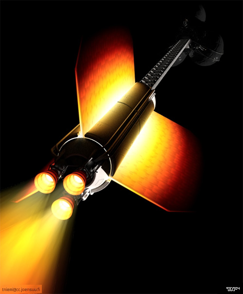
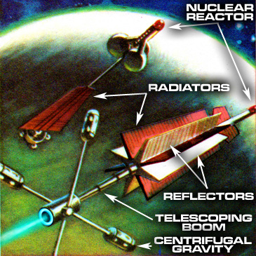

 Power plants and some propulsion systems are going to require heat radiators or the ship will glow red then melt (NO, for the millionth time you CANNOT get rid of the heat by turning it into electricity!).
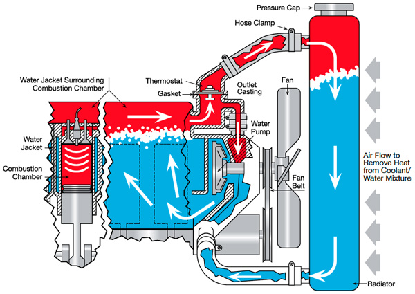
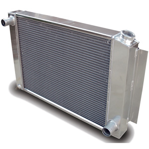
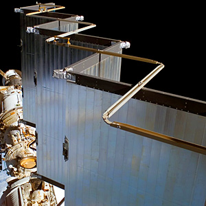


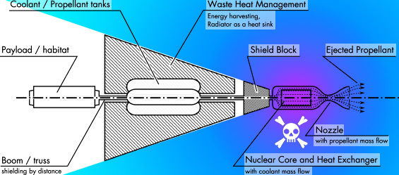


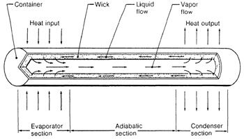
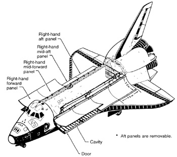
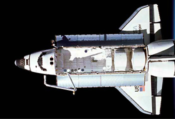
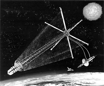
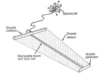
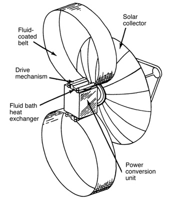


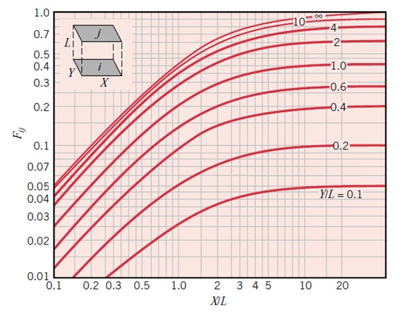
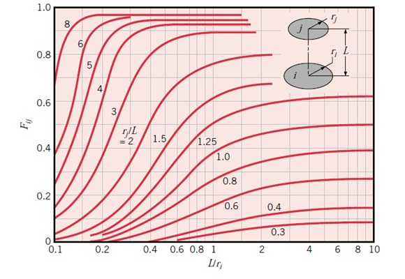
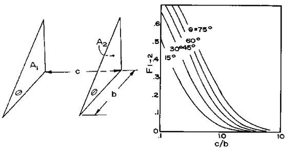


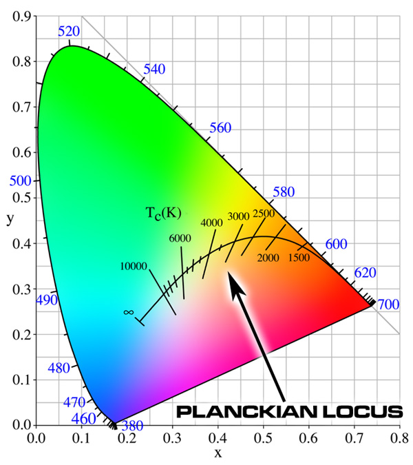
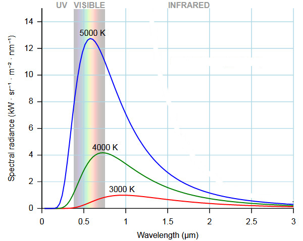

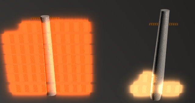
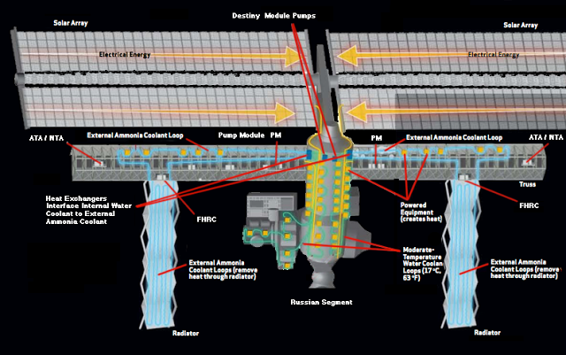
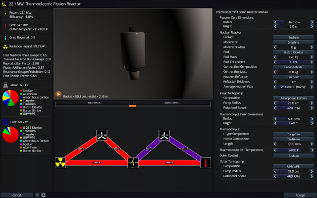
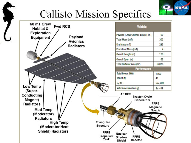
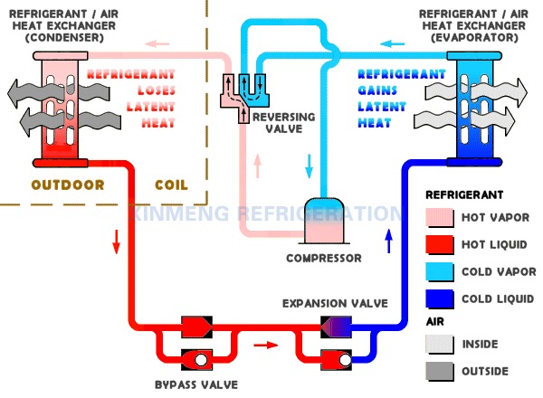
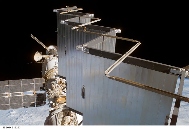
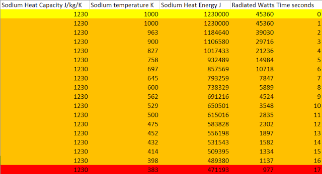
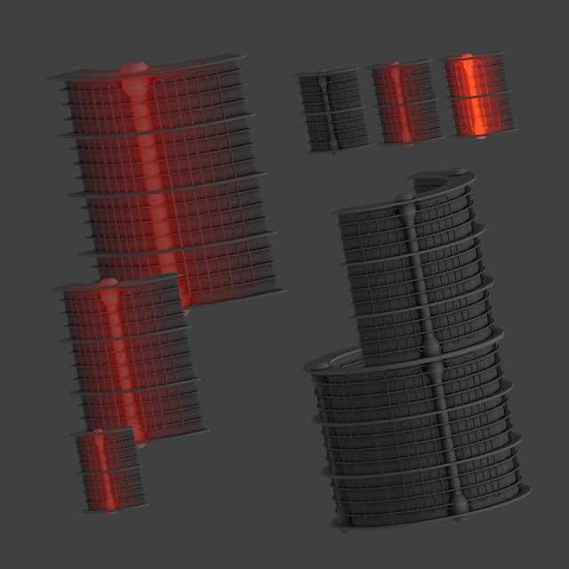
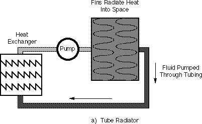
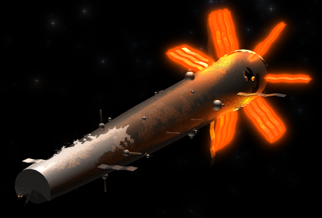

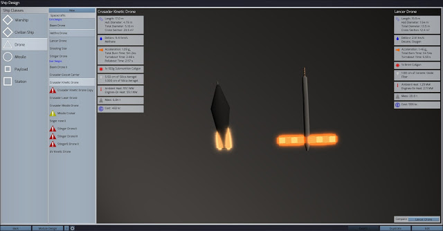


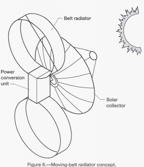
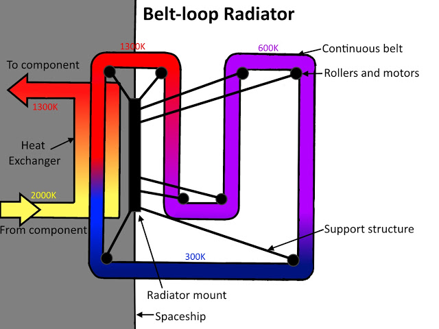
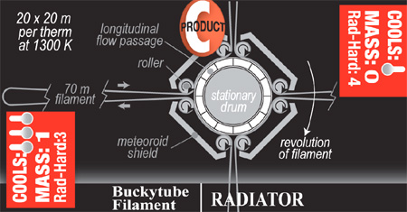
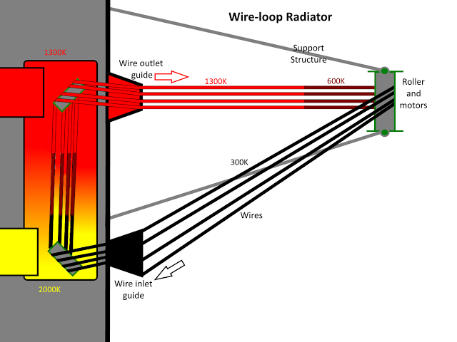
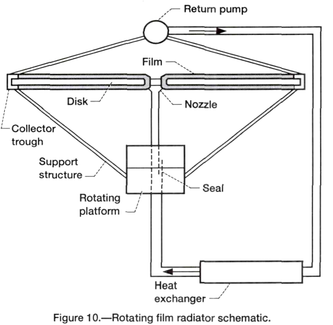


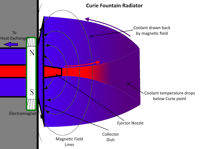
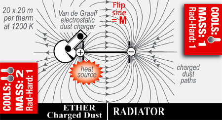
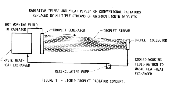
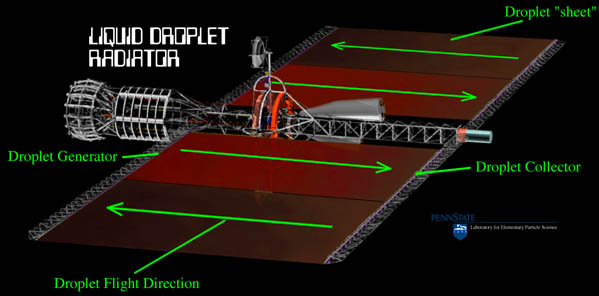
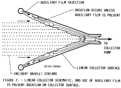
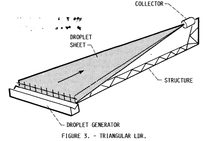
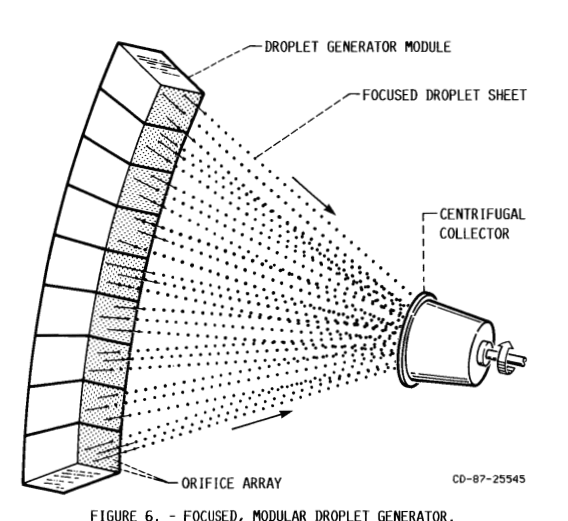
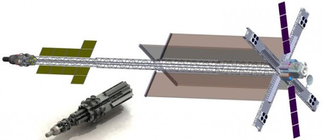
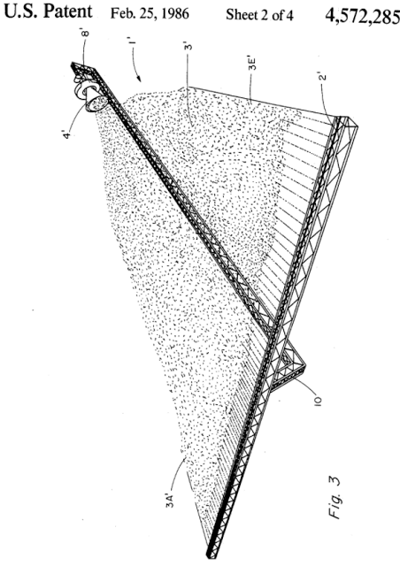
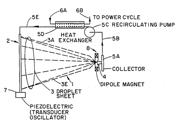
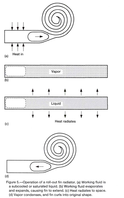
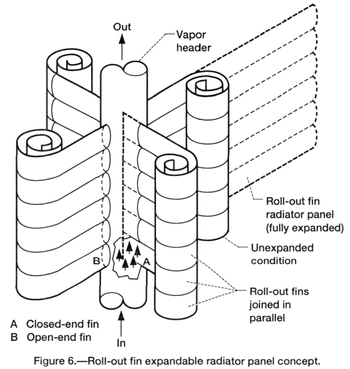
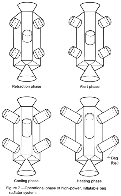
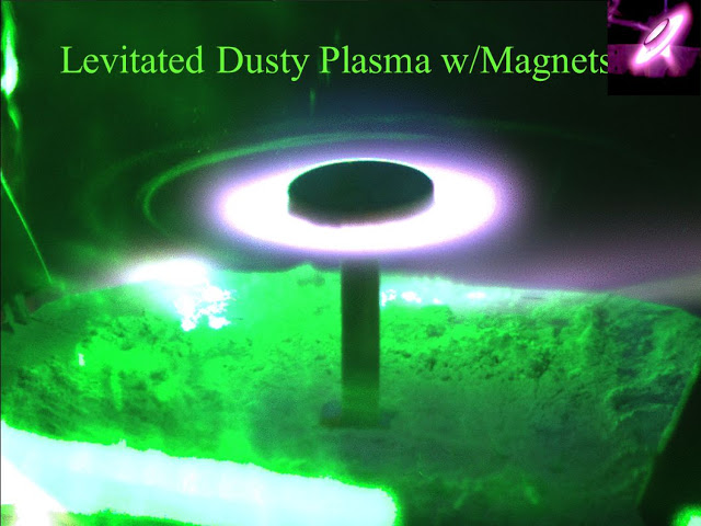
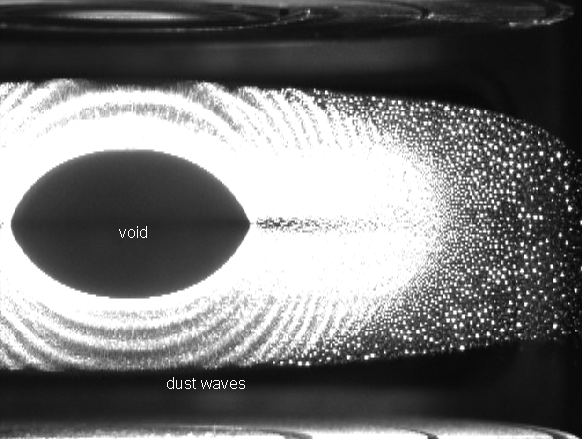
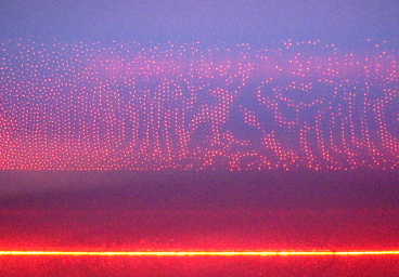
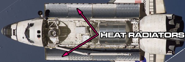

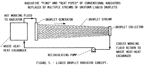
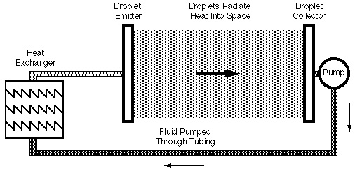
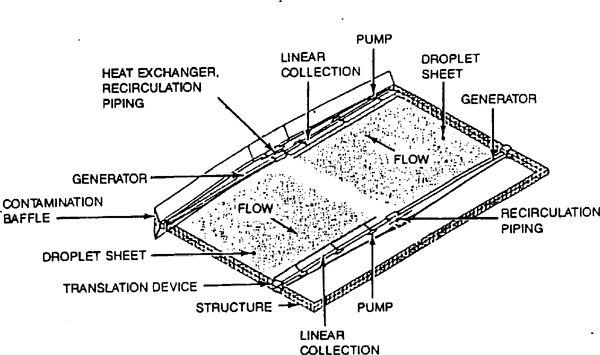
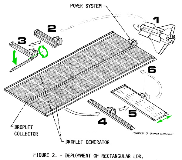
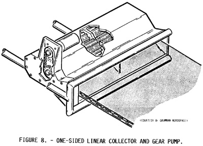

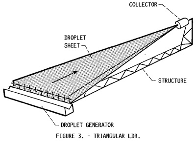
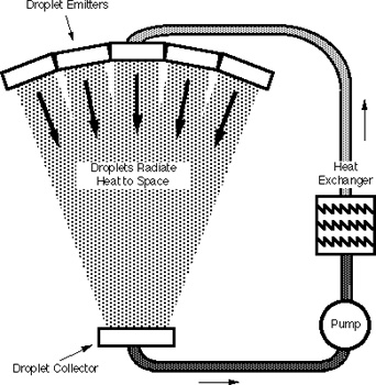
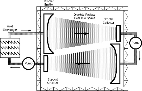
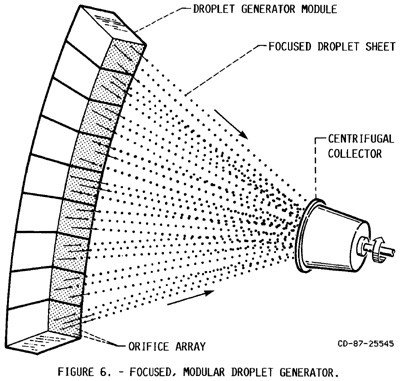
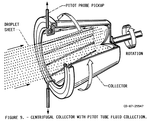
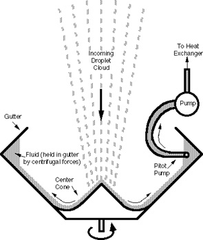
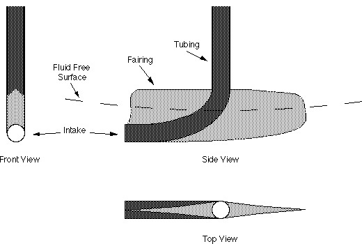
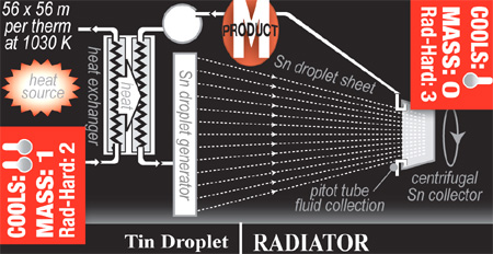


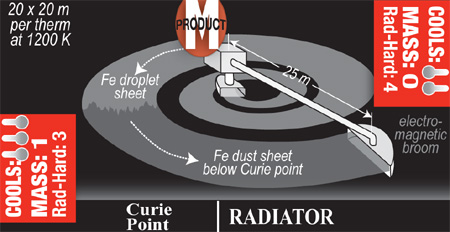
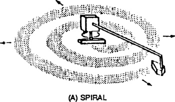
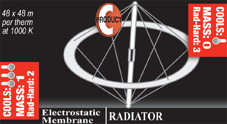
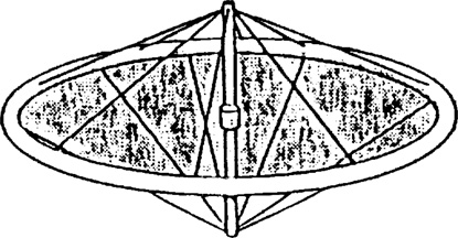


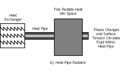
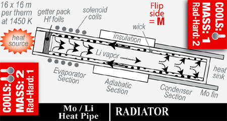
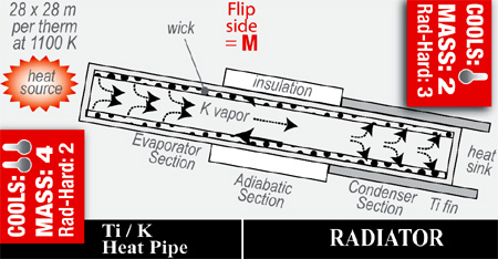
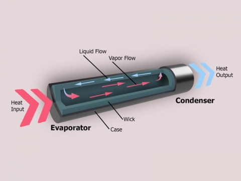
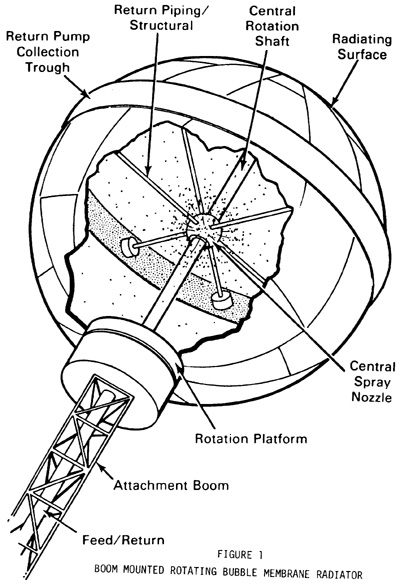
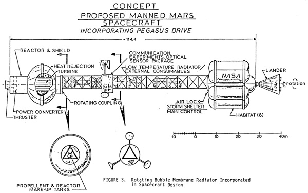
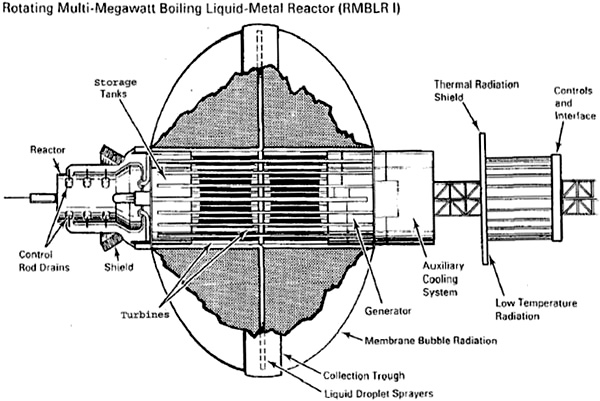
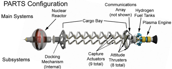
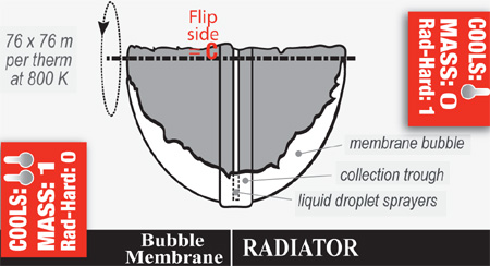

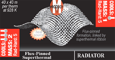
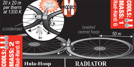
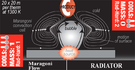
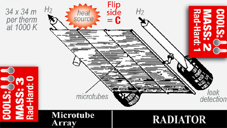
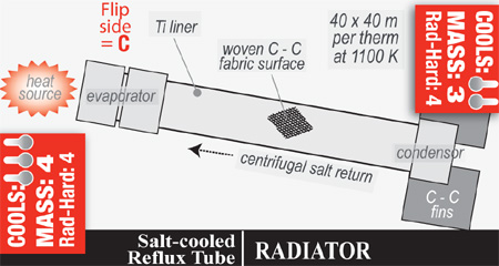
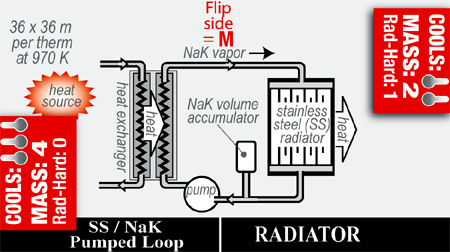

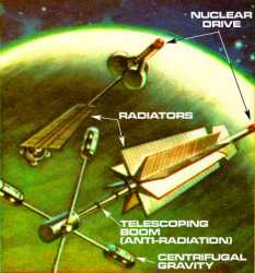
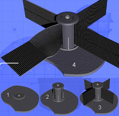


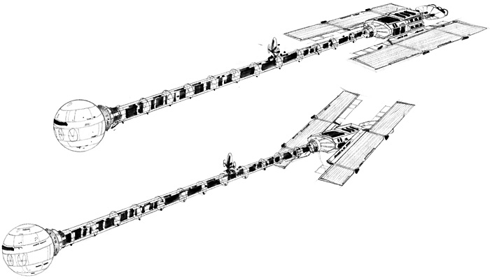
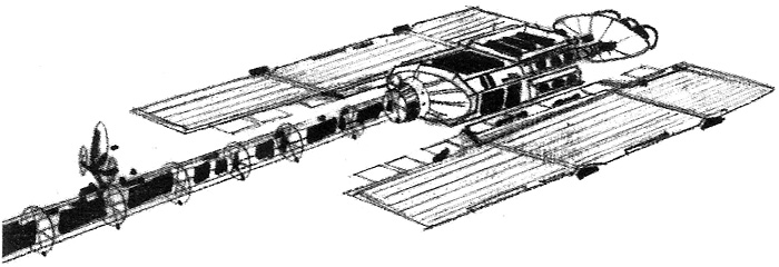
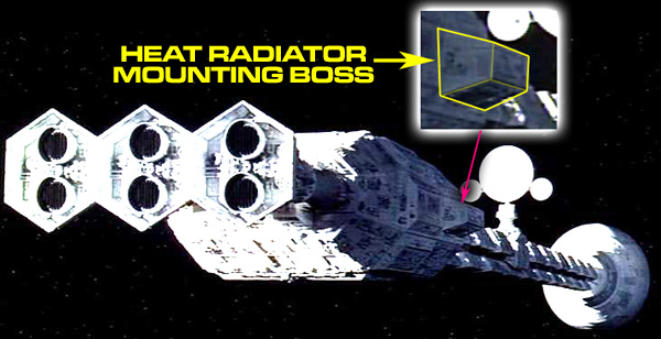
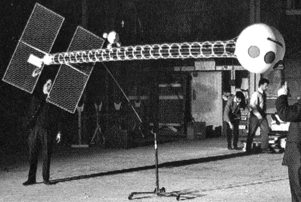
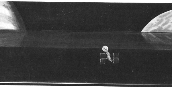
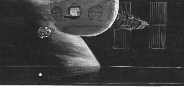
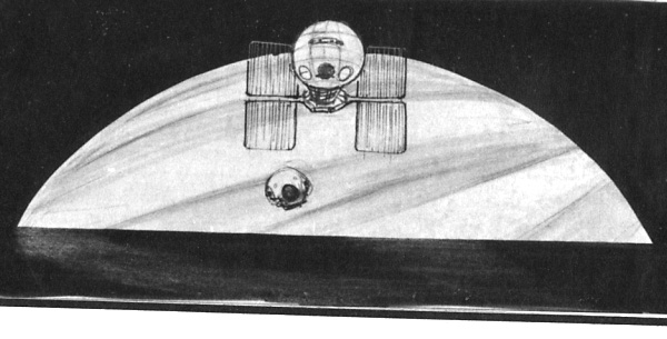
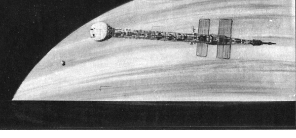
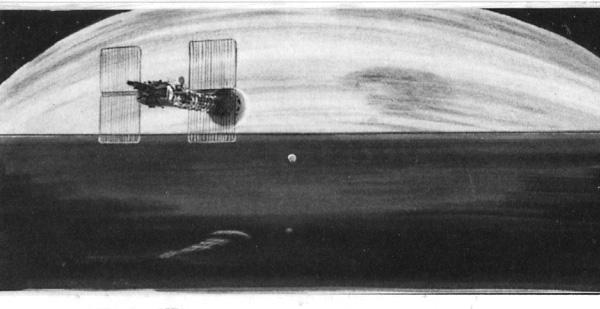


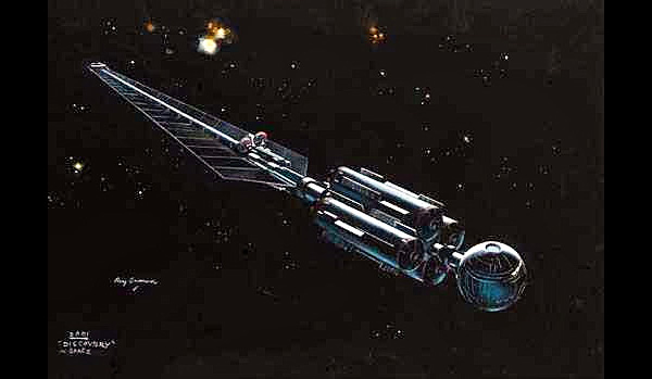

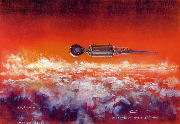
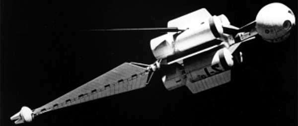

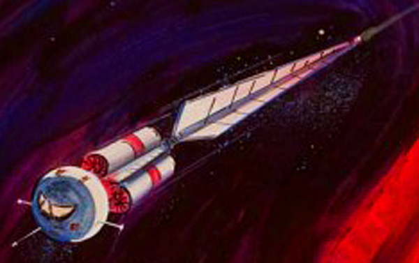


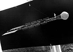
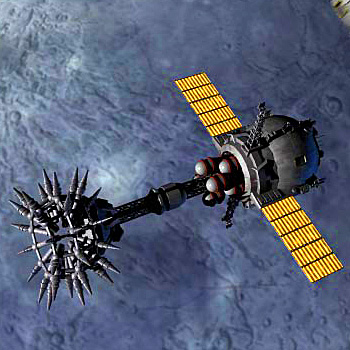
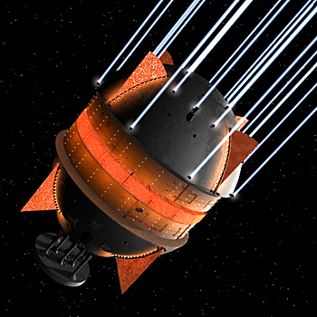
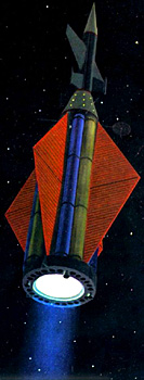

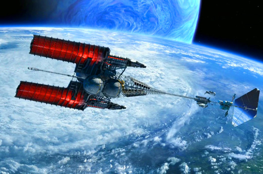
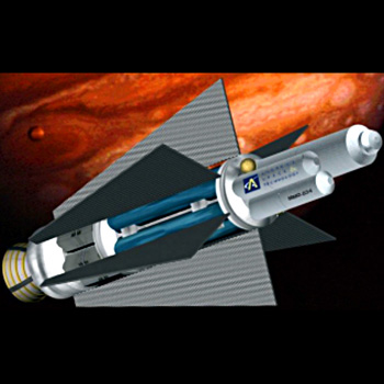
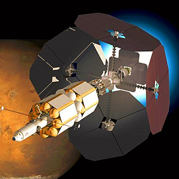
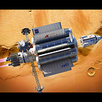
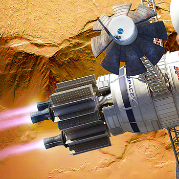
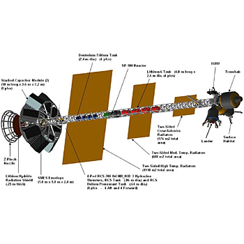
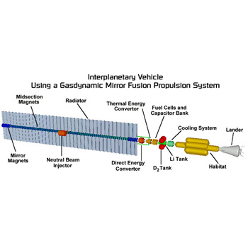
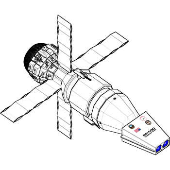
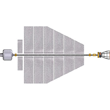
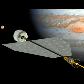
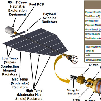
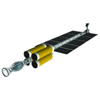
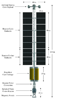
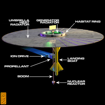

