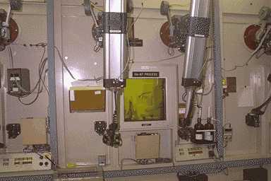
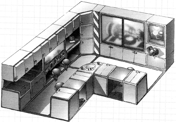
What's in the engine room? The control console for the reactor and the control console for the propellant pumps. Plus the controls to the remote waldoes/robot who fix things in the radioactive section. Damage control equipment and related items.
Remember, outside the engine room hatch will be a decontamination booth. And I'm sure over the hatch will be mounted an alarm with a red rotating light, so you don't have to put your ear on the bulkhead to hear Astro say "Oh SH*****T!!!". Past the hatch will be a radiation-shielded corridor, with a dog-leg bend in it, so you can get in but radiation cannot get out (radiation has to travel in straight lines, but crewmen can zig-zag). Be sure you are wearing your dosimeter. And you might want to get a raycat as a mascot.
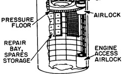
The shadow shield will be in the floor, with the engine(s) below that.
Around the engine deck will be auxiliary propellant tanks. The main tanks provide propellant, which is also used to cool the reactor and keep it from melting. In case something happens to the main tanks, the auxiliary tanks give Astro a few precious seconds of coolant time so he can SCRAM the reactor. The engine deck will also have some kind of Geiger counter to warn the crew of a radiation leak. There will also be controls for the ship's power plant, whether the power is tapped from the propulsion system or from a separate unit.
DOG-LEG BEND
(ed note: Interstellar explorers from Terra land on a newly discovered planet. There are remarkably humanoid primitive aliens living there. The ship's linguist Kung Su learns the alien language, which is suspiciously similar to Chinese. Captain Griffin has a talk with some natives, and learns some interesting bits of the alien's history.)
"Kung," Griffin asked over coffee next afternoon, "how well up are you on Chinese mythology?" "Oh, fair, I guess. It isn't my field but I remember some of the stories my grandfather used to tell me." "What is your legend of creation?" Griffin persisted. "It's pretty well garbled but I remember something about the Son of Heaven bringing the early settlers from a land of two moons on the back of his fire-breathing dragon. The dragon got sick and died so they couldn't ever get back to heaven again. There's a lot of stuff about devils, too." "What about devils?" "I don't remember too well, but they were supposed to do terrible things to you and even to your unborn children if they ever caught you. They must have been pretty stupid though; they couldn't turn corners. My grandfather's store had devil screens at all the doors so you had to turn a corner to get in. The first time I saw the lead baffles at the pile chamber doors on this ship it reminded me of home sweet home. By the way, some young men from the village were around today. They want to work passage to the next planet. What do you think?"
(ed note: The punchline is that Terran Chinese are descendants from the same primitive aliens, who incidentally can be found on thousands of other planets. They moved from planet to planet by hitchhiking in atomic space ships of an extinct high-tech race of "Barbarians".)
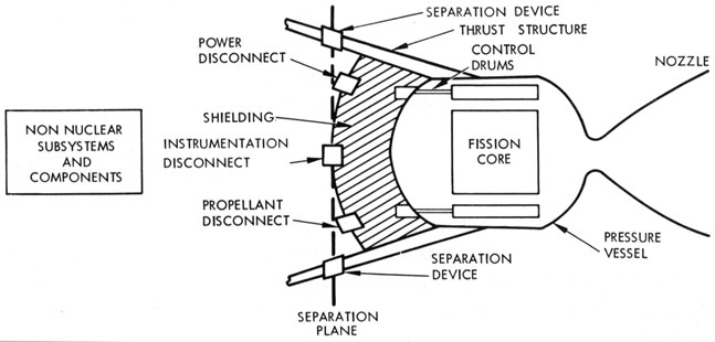
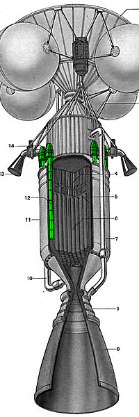
Reactor jettison. From NUCLEAR SPACE PROPULSION by Holmes F. Crouch.
There will also be controls for the flow rate of propellant, and pyrometer (temperature) gauges with helpful red bands labeled "DANGER - MELTDOWN IMMINENT!". There will be a large red "discoverer" button which activates the "there's been a nuclear oopsie" alarms, right next to the even bigger button marked "SCRAM", which is the emergency reactor shutdown. Some say the term is an acronym for Safety Control Rod Axe Man, i.e., the guy who axes the ropes in order to plunge the cadminum damper rods back into the pile. Other say that acronym is a bunch of baloney, you decide.
But there will be one even bigger red button, marked "PANIC!". This one activates the explosive bolts and JATO units that jettison the reactor out the stern of the spacecraft, hopefully removing the spacecraft from the lethal radius. The reactor isn't going to explode like a nuclear weapon, it will just act like a midget neutron bomb, utterly destroying all life on the ship except for the cockroaches.
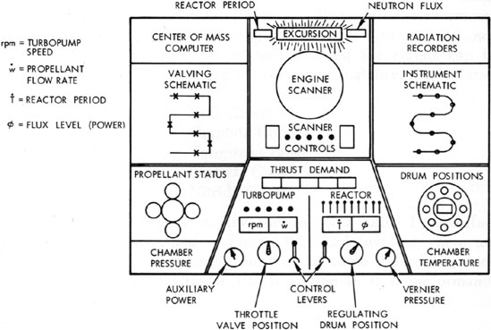
Atomic Rocket Engineer Control Console
Engineer console from NUCLEAR SPACE PROPULSION.
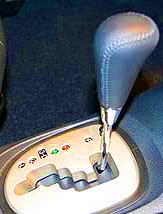
Stepped notches.
This amusing example of 1960's style user interface design is from NUCLEAR SPACE PROPULSION by Holmes F. Crouch (1965). This complements the Pilot's console from the same book. This design assumes that it is for a solid-core nuclear thermal rocket.
Mr. Crouch decided that controlling the rocket's trajectory while simultaneously juggling the power levels of the nuclear reactor was a little too much to ask of a single human being. Each subsystem has too many displays, control functions, and automatic interlocks. So he split it into two jobs: Pilot and Engineer. The Pilot will send the Engineer a request for a certain thrust level. The Engineer will do their best to adjust the engine to produce said thrust; without the engine melting down, exploding, or doing anthing else drastic,
Presented here is the control console for the engineer.
According to Mr. Crouch, there are four independent subsystems involved with flying a nuclear thermal rocket:
Thrust vectoring (Engine exhaust nozzle)
Spacecraft orientation and stability (Attitude jets)
Heat generation for specific impulse (Reactor)
Propellant flow (Turbopump)
The pilot will be controlling the thrust vectoring and spacecraft orientation, the engineer will be controlling heat generation and propellant flow. So the pilot is flying the rocket, while the engineer is flying the reactor and turbopump.
Front and center is the Engine Scanner. This would display the outputs of the various closed-circuit TV scanners, infared mappers, microphone pickups, lights, and periscopes built into the propulsion system to allow the engineer to keep tabs on everything. In addition, multichannel recorders would provide visual displays of engine data, calibration curves, and nuclear radiation profiles. The data plotters would allow the engineer to spot any dangerous trends. The engineer would be particularly interested in displaying computations of fission product inventory and the changing center-of-mass due to propellant sloshing and consumption.
Below the scanner is the thrust demand indicator. This displays the thrust mode order given by the pilot via their thrust mode selector. Again, this is basically a glorified Engine Order Telegraph from the age of steam. The pilot uses it to tell the engineer what sort of thrust is required. It is then the engineer's job to juggle the reactor control rod and the propellant turbines to produce what is requested.
The engineer has two control levers. The right directs the reactor, the left directs the turbopump. These are one-axis levers with stepped notches for shim settings and vernier knobs for trim settings (i.e., a dial on the top of the lever for fine tuning). What it boils down to is that the right lever controls the rocket's exhaust velocity, and the left lever controls the rocket's propellent mass flow. The constraint is that the engineer cannot set the two levers to values that will cause the reactor to melt or the turbopump to explode. Or "flood the engine", that is, feed so much propellant that the reactor can't heat it all so the exhaust is lukewarm.
More on Engineering Tasks, and Math
I'm about to go into more detail about the engineer's task, with equations and everything. If you feel your eyes starting to glaze over, skip past this section.
So, say the pilot calls for an acceleration of 0.1 meter per second (about 0.01 g). By keeping careful tabs on everything that leaves the ship (which is mostly a matter of tracking propellant mass expended), the engineer knows the ship's current mass.
F = A * Mi
where:
F = Thrust (Newtons)
A = ship Acceleration (m/s) {divide by 9.81 for Gs}
Mc = ship's Current Mass (kg)
If the good ship Polaris has its tanks topped off, it has a current mass of 181,000 kilograms. To have an acceleration of 0.1 m/s will require a thrust of 0.1 * 181,000 = 18,100 Newtons. Now, to generate those Newtons:
F = mDot * Ve
where:
F = Thrust (Newtons)
mDot = Propellant Mass Flow (kg/s) { left lever }
Ve = Exhaust Velocity (m/s) { right lever }
So the engineer has to set the turbopump (propellant mass flow) and reactor temperature (exhaust velocity) such that the two produce a thrust of 18100 Newtons. With the added constraint that there is an upper limit on what level of propellant mass flow the turbopump can put out (before it explosively delaminates) and an upper limit on the reactor temperature (before it either melts or has a criticality accident). There is also a limit on how many kilograms of propellant that the reactor can heat up to full temeperature in one second. Try to feed more and the exhaust will be lukewarm, causing the thrust to suffer.
Ve is proportional to the square root of the reactor temperature. This means that to double the exhaust velocity, you have to raise the reactor temperature four times. The approximate equation is:
Qe = (Ve / (Z * 129))2 * Pw
where
Qe = engine reaction chamber temperature (Kelvin)
Ve = exhaust velocity (m/s)
Z = heat-pressure factor, varies by engine design, roughly from 1.4 to 2.4 or so.
Pw = mean molecular weight of propellant, 1 for atomic hydrogen, 2 for molecular hydrogen
I have some very shakey figures that I calculated myself (and are therefore suspect) that suggest a NERVA/Dumbo style solid core have a maximum temperature of around 2,300° K, a Cermet core up to 2,800° K, and a pebble bed up to around 3,000° K. I saw another figure that implied a theoretical maximum of about 4,700° K, but I don't trust that figure.
So if the engineer wanted to keep the engine at a conservative 2,000° K, and the engine had a heat-pressure factor of 1.9, that would produce an exhaust velocity of
Qe = (Ve / (Z * 129))2 * Pw solve for Ve Ve = sqrt(Qe / Pw) * (Z * 129) Ve = sqrt(2000 / 2) * (1.9 * 129) Ve = 30 * 245.1 Ve = 7,400 m/s
With that exhaust velocity, to get 18,100 Newtons you'll have to set the turbopumps to do 18,100 / 7,400 = 2.5 kg/s.
As mentioned before, you generally don't care what the ship's acceleration is, except during lift-off and landing. But it is also important if you are in a combat situation, or docking, or otherwise have to change the ship's velocity in a hurry.
Associated with the right lever reactor controller, there would be readouts of reactor period, neutron flux level, control drum setting including vernier tube setting, net reactivity worth, rate of temperature change, and temperature levels.
Associated with the left lever turbopump controller, there would be readouts of pump speed, discharge pressure, propellant flow rate, amount of propellant onboard, core bypass valve positions, and quality of propellant going into the reactor core.
Finally would be the dire warning of the "risk-of-excursion" light, at the very top ("excursion" is a technical term for "nuclear reactor criticality accident" ). This alerts the engineer that the reactor is at risk of a criticality and they had better do something about it fast! The "reactor period" readout displays the dangerous decreasing reactor period. The smaller the reactor period, the more rapid the change in reactor power level. The neutron flux readout shows the current reactor power level. If it goes too high, the reactor emits a deadly burst of neutrons and everybody dies.
Propulsion
WAR EMERGENCY POWER
War Emergency Power (WEP) is an American term for a throttle setting on some World War II military aircraft engines. For use in emergency situations, it produced more than 100% of the engine's normal rated power for a limited amount of time, often about
five minutes. Similar systems used by non-US forces are now often referred to as WEP as well, although they may not have been at the time, as with the German Luftwaffe's Notleistung and Soviet VVS' forsazh systems.
WEP in World War II aircraft
Maximum normal power would be limited by a mechanical stop, for instance a wire across the throttle lever slot, but a more forceful push would break the wire, allowing extra power. In normal service, the P-51H Mustang was rated at 1,380 hp, but WEP would deliver up to 2,218 hp, an increase of 61%. In the P-51D Mustang, the model most produced and used during World War II, the WEP increased the HP from 1490 to 1720. The Vought F4U Corsair, not originally equipped for WEP, later boasted a power increase of up to 410 hp (17%) when WEP was engaged. Several methods were used to boost engine power by manufacturers, including water injection and methanol-water injection. Some earlier engines simply allowed the throttle to open wider than normal, allowing more air to flow through the intake. All WEP methods result in greater-than-usual stresses on the engine, and correspond to a reduced engine lifetime. For some airplanes, such as the P-51D, use of WEP required that the engine be inspected for damage before returning to the air. 5 hours' total use of WEP on the P-51D required a complete tear-down inspection of the engine.
British and Commonwealth aircraft could increase power by increasing the supercharger boost pressure. This modification was common by the summer of 1940, with the widespread availability of 100 octane fuel. Raising supercharger boost pressure from 6 lb to 12 lb increased the Merlin III engine rating to 1310 hp, an increase of over 250 hp. Pilots had to log the use of emergency boost and were advised not to use it for more than 5 minutes continuously.
The German MW 50 methanol-water injection system required additional piping, as well as a storage tank, increasing the aircraft's overall weight. Like other boost techniques, MW 50 was restricted by capacity and engine temperatures and could only be used for a limited time. The GM 1 nitrous oxide injection system, also used by the Luftwaffe, provided extreme power benefits of 25 to 30 percent at high altitude by adding oxidizer gases but required cooling on the ground and, like the MW 50 boost system, added significant weight. One of the few German aircraft that could be equipped with both Notleistung systems, the late war Focke-Wulf Ta 152H high-altitude fighter, could attain a velocity of some 756 km/h (470 mph) with both systems used together. Kurt Tank reportedly once did this, using both boost systems simultaneously when he was flying a Junkers Jumo 213E-powered Ta 152H prototype fitted with both MW 50 and GM-1, to escape a flight of P-51D Mustangs in April 1945.
Modern times
Perhaps the most dramatic WEP feature was found in the MiG-21bis fighter jet. This late variant of the standard Soviet light fighter plane was built as a stopgap measure to counter the newer and more powerful American F-16 and F/A-18 fighters until the next-generation MiG-29 could be introduced to service.
The MiG-21bis received the upgraded Tumansky R-25 engine, which retained the standard 42 / 65 kN normal and forsazh power settings of earlier R-13 powerplants, but added a second fuel pump to supply the new super-afterburning system with jet fuel. Use of this "diamond regime" provided a massive 97.4 kN of thrust for no more than 3 minutes in actual wartime use. Use of this temporary power gave the MiG-21bis slightly better than 1:1 thrust-to-weight ratio and a climbing rate of 254 meters/second, equalling the F-16's nominal capabilities in close-quarters dogfight.
In air combat practice with the MiG-21bis, use of WEP thrust was limited to one minute, to reduce impact on the engine's 800 flight hours lifetime, since every second of super-afterburner use counted as several minutes of regular power run due to extreme thermal stress. When WEP was on, the R-25 engine produced a huge 5 meter long blowtorch exhaust - the six or seven brightly glowing rhomboid "shock diamonds" visible inside the flames gave the emergency-power setting its "diamond regime" name.
WEP in surface vehicles
Some modern military surface vehicles also employ WEP features. The US Marine Corps Expeditionary Fighting Vehicle (cancelled in 2011) sported a 12-cylinder 1200 bhp diesel engine developed by the German MTU company. When the EFV is swimming the powerplant can be boosted to 2700 hp via the use of open circuit seawater-cooling. Such extreme war power setting allows the MTU engine to drive four massive water-jet exhausts which propel the surface-effect riding EFV vehicle at sea speeds reaching 35 knots.
Although the EFV prototypes demonstrated revolutionary performance on water and land, the reliability of their extremely boosted powerplants
never met stringent military standards and the vehicle failed to enter Marine Corps service.
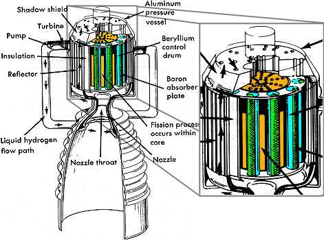
Nuclear fission reactors are throttled by controlling the amount of neutrons available in the core. "Thermal neutron" reactors need slow moving neutrons, "Fast neutron" reactors use fast ones. Basically this means that a thermal neutron reactor has the fission fuel elements embedded in a "moderator", which turns fast neutrons into thermal neutrons. In both designs, the reactor is generally encased in a neutron reflector. This intercepts neutrons on their way out of the reactor and sends them back in, "kicking them back into play" so to speak. This lowers the amount of fission fuel you need in order to sustain a chain reaction.
The amount of free neutrons available is controlled by the dampers. In a NERVA engine, these are rods of cadmium or other neutron poison inserted or removed from the reactor to control the chain reaction. Make sure they are not warped. A non-automated set-up will have the dampers positioned by hand using a "multiplying vernier" and a "danger gauge". The gauge tells you how hot the reaction is. Verniers tell how far a given damper has been inserted into the reactor. Pull the dampers out slowly until the danger gauge tells you the reaction is at the desired level.
Side note: a vernier is what they used to use back in the ancient days before digital read-outs. Standard gauges have a pointer that runs along a scale. A vernier is a clever way to increase the accuracy of the scale.
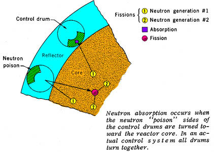
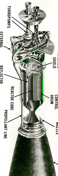
Control drums around the reactor body.
Core is gold, drums are blue, with a green neutron-poison segment.
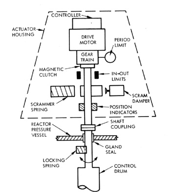
Control Drum Actuator those mushroom-shaped gadgets atop each control drum
Control Drums
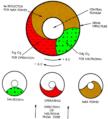
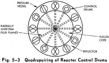
In some NERVA designs, instead of rods of cadmium inserted into the body of the reactor, they instead have drums imbedded in the neutron reflector around the body of the reactor. One side of the drums are composed of neutron reflector, the other side is composed of neutron absorbers (AKA "neutron poison"). If the reflector side of the drums are facing the reactor, enough neutrons are reflected to sustain the chain reaction. If the absorber side is facing, it sucks up the neutrons and there are not enough neutrons to sustain the reaction. The control drums are rotated to partial positions in order to throttle the reaction to desired levels. The drums are rotated by the "control drum actuator", which look like a metal mushroom, one atop each control drum.
In both cases you want a damper fail safe, so if anything happens the failure modes will tend to make the dampers slam in to the full "quench reaction" position.
There will be damper safeties. When no acceleration is expected for some time, these lock the dampers in the full-quench position.
Atomic Engine Startup
Solid-Core Startup
The following description is for a solid core fission engine, and is adapted from NUCLEAR SPACE PROPULSION by Holmes F. Crouch (1965).
Say the engineer gets the command from the pilot to prepare for a burn. The engineer "preconditions" the turbopump and the reactor so they are able to generate thrust on command, they are in the state called "idling." The turbopump is idling with its discharge bypassed back to its suction side. The propellant lines into the reactor have been chilled down and bleed close-loop flow is maintained. The reactor is nuclearly critical but the core is "dry", it has no propellant in it.
The fun starts when you try to actually make this contraption generate thrust.
Transients Oscillations
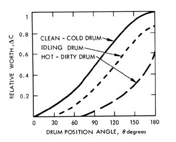
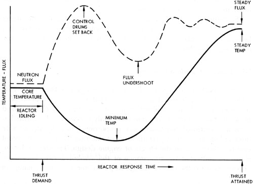
You are changing from a dry core to a wet core, one that has propellant flowing through it. The core is both very hot with heat and very hot with neutron radiation. And the liquid hydrogen propellant is both very cold (we are talking a freaking minus 252° Celsius here) and also a pretty good neutron moderator. So when the cold propellant hits the hot reactor two things happen, and both are rather drastic. There is a nuclear disturbance and a thermal disturbance. Both create transients oscillations that can destroy the engine if they are not controlled. See Figure 1.
The nuclear and thermal disturbances are linked because both are caused by the liquid hydrogen propellant. The more LH2, the more it moderates worthless fast neutrons into fission-causing thermal neutrons, thus drastically increasing the fission rate. Also the more LH2 the more the cryogenically cold stuff thermally cools the red-hot reactor core.
This is the single most deadly problem in nuclear thermal rocket design. Among designers, more attention has been given to this subject, "Engine Dynamic Stability," than to any other aspect of thrust control. This is why the ship's engineer has prematurely gray hair.
Figure 1
Neutron flux and core temperature as the engine begins producing thrust.
The nuclear transient is due to the unfortunate fact that the liquid hydrogen propellant is a pretty good moderator. The dry reactor has the control drums set so the core has enough thermal neutrons to sustain a moderate chain reaction. The flood of propellant abruptly skyrockets the number of thermal neutrons, which abruptly skyrockets the chain reaction. The chain reaction "thermostat" automatically reacts to the sudden rise in neutron flux, and quickly rotates the control drums to cool off the reaction (in Figure 1 at point "Control Drums Set Back").
This causes a flux undershoot as the drums over-correct (in Figure 1 at point "Flux Undershoot").
The thermostat then over-corrects while attempting to bring the chain reaction up to the desired level, which causes a flux overshoot. If the engine designer has done their job correctly, these oscillations die down to a steady flux at the desired level. If they have not done their job correctly, the runaway oscillations increase until the reactor melts or has a criticality accident. The runaway nuclear oscillations would also make runaway thermal oscillations, compounding the disaster.
The thermal transient occurs because the initial flood of sub-zero propellant extracts heat from the idling reactor core faster than the heat can be resupplied. This lowers the core temperature. The temperature drops until the heat from the rising chain reaction increases enough to stop it (in Figure 1 at point "Minimum Temp"). If the temperature oscillation is not controlled, they could create pressure oscillations in the propellant. These pressure oscillations can be transmitted upstream where they could damage the turbopump. And the pressure oscillations can affect the moderating characteristics of the propellant, which would affect the nuclear oscillation.
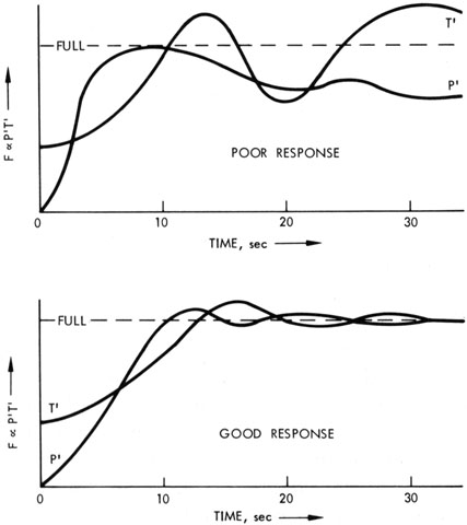
Figure 2
A good response is when the twin oscillations level off
A poor response is when the oscillations reinforce each other and destroy the engine
If everything goes according to design, the twin oscillations die out and level off. If the engineer's luck has run out, the twin oscillations reinforce each other and the engine has a simultaneous criticality accident and a reactor core melt down.
What makes this so deadly is the fact that the thermal oscillations can affect the nuclear oscillation and vice versa. If the oscillations start to amplify each other you are doomed. This also means that as the engineer tries to damp out one oscillation the procedure might make the other oscillation worse.
There are equations for these transients, but most of them are differential equations so I'm not going to bore you with them. You can find them in Dr. Crouch's book.
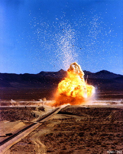
A Kiwi nuclear thermal rocket purposely destroyed in a test.
A Kiwi nuclear thermal rocket test (1965). This was a deliberate destruction test. The safety experiment was designed to obtain basic reactor shutdown information for use in predicting the behavior of nuclear rocket reactors under a wide range of accident conditions. It detonated with a nuclear explosion yield equivalent to 2.1 tons of TNT, and reached a maximum temperature of 4,250° K, which vaporised 5% of the reactor core fuel rods, of which 68% was dispersed as fallout with a specific activity of 1015 fissions/gram for refractory nuclides like Zr-95.
NERVA ROCKET ENGINE DETAIL SPECIFICATION
(ed note: Apparently this is a preliminary document. Many of the performance values are indicated as TBD or value To Be Determined at a future date)
Section l. SCOPE
This part of this specification defines the requirements for the
performance, design, and qualification of equipment identified as the NERVA
Nuclear Rocket Engine, Contract End Item (CEI) No. 90290 as established by
the NERVA Program Requirements Document, SNPO-NPRD-1. This CEI, hereinafter
referred to as the engine, is used as a source of primary propulsive
power for both manned and unmanned space vehicle applications. The engine
is designed to operate at a vacuum thrust level of 75,000 lbs (330,000 Newtons) and a specific
impulse of 825 seconds (exhaust velocity 8,090 m/s) and shall be man rated. The engine requires externally
supplied liquid hydrogen, command signals, and electrical power. Rated thrust
is achieved at a nominal thrust chamber pressure of 450 psia and a nominal
design thrust chamber temperature of 4250° Rankine and with a nozzle having
an expansion ratio of 100:1. Endurance at rated temperature shall be 600
accumulated minutes. The operating time is utilizable in multiple cycles up to
60 with durations of varying lengths up to 60 minutes.
1.1 Mission Definitions — The following missions are used in the definition
of NERVA requirements. Payloads shall be maximized consistent with
the engine performance requirements of this specification.
Reusable Interorbit Shuttle — To shuttle payloads (manned
and unmanned) between a 262 nautical mile earth orbit (485 km) and a space station in
lunar or geosynchronous earth orbit and return for reuse.
Unmanned Deep-Space Injection — To place a large unmanned
payload on a deep space trajectory using the reusable nuclear shuttle from
262 nautical mile earth orbit and returning the shuttle vehicle to earth orbit
for reuse.
3.1.1.1.1 Operational Modes — The engine shall be capable of performance
as specified in 3.1.1.1.5, (Impulse and Controllability Requirements) while
operating in the following modes: (See Section 6.2 for definition of operational
modes.)
Normal Mode
Malfunction Mode
Single Turbopump Operation
Component Malfunction
Emergency Modes
3.1.1.1.2 Vacuum Performance Rating — The engine performance rating is
based on nominal vacuum thrust using liquid hydrogen as specified in MSFC
Specification 356 with a 100:1 nozzle area ratio as follows:
Thrust — 75,000 ± 2000 lb which includes a ± 1500 lb controllability
tolerance. (Thrust considered parallel to the pressure vessel axis).
Specific Impulse — 825 sec ±0.75% (which includes ± TBD %
controllability tolerance but does not include allowable operating H2 leakage
nor H2 required for tank stage operation) Minium Specific Impulse — 819 s with flight vehicle Isp trim signal.
Nominal Chamber Pressure - 450 psia (The nominal chamber
pressure is the stagnation pressure).
Nominal Chamber Temperature - 4250°R (The nominal chamber
temperature is the stagnation temperature).
Normal Mode Endurance - 600 minutes at rated temperature (accumulated
in up to 60 cycles of varying duration up to 60 minutes maximum per
cycle).
In meeting the thrust and impulse requirements all components
must perform within their specified tolerances.
3.1.1.1.3 Operational Constraints — The engine shall be capable of
operating at any selected point within the operational constraint map shown
in Figure 1.
During thrust buildup and retreat, the engine shall be capable
of chamber temperature ramp rates of 150 ± 25°R/sec and chamber pressure ramp
rates of TBD psi/sec at a pressure less than 293 psia and at a rate of 50 ± 10
psi/sec at a pressure greater than 293 psia.
3.1.1.1.5.1 Normal Mode Impulse — The engine shall be capable of meeting
the following performance requirements when operating in the normal mode. The
normal operating cycle shall be initiated by a vehicle command signal to depart
from a coast (shutdown) condition or previous operating cycle and is completed
upon termination of cooldown flow, post operational status checks and coast
preparation, i.e., system power-down, or the receipt of a command signal for
restart. The normal operating cycle is shown in Figure 2.
click for larger image
3.1.1.1.5.1.1 Prestart — The engine shall be capable of performing function
and status check operations as commanded to assure readiness for startup. There
shall be no propellant flow other than permitted by 3.3.1.8 (Leakage) during prestart
operations except as required for cooldown during restart. Prestart time
shall be TBD + TBD minutes.
3.1.1.1.5.1.2 Startup — Startup consists of temperature conditioning,
nuclear startup, bootstrap, and thrust buildup. Startup is initiated upon
receipt of a command signal to initiate propellant flow or nuclear startup
and is completed when rated performance has been achieved within the specified
controllability limits. The engine shall be capab1e of accomplishing temperature
conditioning and nuclear startup simultaneously or sequentially depending on
prior operating history. The engine shall be capable of meeting the following
requirements during normal startup operations.
3.1.1.1.5.1.2.1 Temperature Conditioning and Nuclear Startup.
3.1.1.1.5.1.2.1.1 Temperature Conditioning — Temperature Conditioning is
initiated at engine startup and consists of non-nuclear component and reactor
thermal conditioning. These operations may be conducted separately or simultaneously
depending on engine thermal conditions at startup. The engine shall
be capable of being temperature conditioned for the initiation of bootstrap
within TBD seconds and shall consume less than TBD lbs of propellant during this
time. The time required for this function shall be predictable within + TBD
seconds and propellant consumtion shall be predictable within + TBD lb.
3.1.1.1.5.1.2.1.2 Nuclear Startup — Nuclear startup may occur separately
or simultaneously with temperature conditioning. During nuclear startup
reactor criticality shall be achieved and temperature control shall be
established. The time required for this function shall not exceed TBD sec and
shall be predictable within TBD sec for each nuclear startup.
3.1.1.1.5.1.2.2 Bootstrap — Bootstrap startup begins with initiation of
flow through the turbines, and ends when program control has been achieved to
initiate thrust buildup. Temperature control shall be maintained during bootstrap,
and the engine shall be brought under program control when chamber pressure
has increased to TBD + TBD psia. The engine shall be capable of completing
bootstrap startup within TBD sec and shall consume less than TBD lb of propellant
during this time. These parameters shall be predictable to within + TBD sec
and + TBD lb propellant for each bootstrap startup throughout the engine operating
life.
3.1.1.1.5.1.2.3 Thrust Buildup — The engine shall be capable of thrust
buildup through the engine throttle point, and shall maintain rated specific
impulse from the throttle point to steady state operations. For each thrust
buildup cycle during the engine useful life, the thrust and specific impulse
shall be predictable as a function of time and engine history. These parameters
shall be controllable to + TBD percent thrust and + TBD percent specific impulse
of instantaneous predicted values.
3.1.1.1.5.1.3 Steady State Operation — Steady State Operation is initiated
when rated performance has been achieved within specified controllability limits,
and is terminated by receipt of a command signal to begin retreat from this
condition. During Steady State Operation the engine shall be capable of providing
the vacuum performance specified in 3.1.1.1.2 (Vacuum Performance Rating).
3.1.1.1.5.1.4 Shutdown and Cooldown — Shutdown consists of throttling,
throttle hold, temperature retreat and pump tailoff, and is initiated by a
command signal to depart from rated conditions and is completed upon termination
of powered pump operation. During shutdown the engine shall be capable of steady-state
hold at the engine throttle point. Cooldown is initiated upon completion
of engine shutdown and is completed upon termination of propellant flow or the
receipt of a command signal for restart. Cooldown propellant is supplied at
tank pressure conditions as defined in 3.1.1.1.8, (Propellant Conditioning).
The total delivered impulse during shutdown and cooldown shall be predictable
within + TBD percent of the total startup and steady state impulse as a function
of engine operating history and shall be controllable as a function of time
after initiation of shutdown. Provision shall be made for a TBD sec steady state
hold at the throttle point, and for each shutdown cycle during the engine operating
life the thrust and specific impulse shall be controllable to + TBD percent thrust
and + TBD percent specific impulse of instantaneous predicted values from
initiation of shutdown to termination of steady state hold at the throttle
point. The total impulse delivered after termination of the steady state hold
at the throttle point shall be controllable to within ±20,000 lb sec at termination
of cooldown. The time of termination of cooldown impulse shall be
predictable within ±15 sec. Cooldown thrust shall be not less than 30 lb and
average cooldown specific impulse shall be not less than 400 sec.
3.1.1.1.5.1.5 Post Operations — The post operation period begins with the
termination of cooldown and ends when the engine is powered-down for coast or
space storage. During this period, the engine shall be capable of functional
and status check operations. The time for this operation shall not exceed TBD
minutes. There shall be no propellant flow other than permitted in 3.3.1.8
(Leakage).
3.1.1.1.5.1.6 Coast — The coast operation period is initiated upon completion
of the post operation period and continues until receipt of a signal to
initiate restart operations. During coast operations the engine thrust (due to
allowable non-operating leakage) shall not exceed TBD lb.
3.1.1.1.5.2 Malfunction Mode Impulse — The engine shall be capable of
meeting the following performance requirements when operating under the following
malfunction conditions. The engine shall be capable of direct transition to the
malfunction modes during any phase of engine operation.
3.1.1.1.5.2.1 Single Turbopump Operation Impulse — The engine shall be
capable of operating with one Propellant Feed Subsystem leg inoperative.
Operation in this mode shall be initiated or completed as specified in 3.1.1.1.5.1
(Normal Mode Impulse), or by receipt of a command signal demanding the engine to
switch to this mode of operation from the normal mode startup, steady state or
shutdown functions.
3.1.1.1.5.2.1.1 Prestart — There shall be no propellant flow other
than permitted in 3.3.1.8 (Leakage) during prestart operations except as
required for cooldown during restart. Prestart time shall be TBD + TBD
minutes.
3.1.1.1.5.2.1.2 Startup — The engine shall be capable of the following
requirements during single Turbopump startup operation.
3.1.1.1.5.2.1.2.1 Temperature Conditioning and Nuclear Startup
3.1.1.1.5.2.1.2.1.1 Temperature Conditioning — The engine shall be
capable of being temperature conditioned for the initiation of bootstrap within
TBD seconds and shall consume less than TBD lb of propellant. The time
required for this function shall be predictable within + TBD sec.
3.1.1.1.5.2.1.2.1.2 Nuclear Startup — Nuclear startup may occur
separately or simultaneously with temperature conditioning. During nuclear
startup reactor criticality shall be achieved and temperature control shall be
established. The time required for this function shall not exceed TBD sec and
shall be predictable within + TBD sec for each nuclear startup.
3.1.1.1.5.2.1.2.2 Bootstrap — Bootstrap startup begins with initiation
of flow through the operational turbine, and ends when program control has been
achieved to initiate thrust buildup. Temperature control shall be maintained
during bootstrap, and the engine shall be brought under program control when
chamber pressure has increased to TBD + TBD psia. The engine shall be capable
of completing bootstrap startup within TBD sec and shall consume less than
TBD lb of propellant during this time. These parameters shall be predictable to
within + TBD sec and + TBD lb propellant for any Single Turbopump bootstrap
startup occurring throughout the engine operating life.
3.1.1.1.5.2.1.2.3 Thrust Buildup — For each thrust buildup cycle
during the engine useful life, the thrust and specific impulse shall be
predictable as a function of time and engine history. These parameters
shall be controllable to + TBD percent thrust and + TBD percent specific
impulse of instantaneous predicted values.
3.1.1.1.5.2.1.3 Steady State Operation — The engine when operating with
one PFS leg shall provide the vacuum specific impulse specified in 3.1.1.1.2
(Vacuum Performance Rating) and a nominal vacuum thrust of 60,000 lb. The
engine shall be capable of operation at extended duration as required to deliver
a single burn total impulse equivalent to that which would have been required for
normal mode operation.
3.1.1.1.5.2.1.4 Shutdown and Cooldown — The engine shutdown and cooldown
requirements for this mode of operation shall be as specified in 3.1.1.1.5.1.4
(Shutdown and Cooldown) for normal mode operation.
3.1.1.1.5.2.1.5 Post Operation — The engine post operation requirements
shall be as specified in 3.1.1.1.5.1.5 (Post Operations) for normal mode
operation.
3.1.1.1.5.2.1.6 Coast — During coast operations the engine thrust (due
to allowable non-operating leakage) shall not exceed TBD lb.
3.1.1.1.5.2.2 Component Malfunction Impulse — When operating with
component malfunctions other than those which would cause operation with a single
PFS leg as specified in 3.1.1.1.5.2.1 (Single Turbopump Operation Impulse), or
emergency operation as specified in 3.1.1.1.5.3 (Emergency Mode Operation), the
engine shall be capable of operating under the conditions specified in 3.1.1.1.5.1
(Normal Mode Impulse).
3.1.1.1.5.3 Emergency Mode Operation — The engine shall be capable of
operation in an emergency operating mode. No more than one emergency cycle shall
be required of the engine. The emergency operating modes shall be initiated
manually or by a command from the malfunction detection and control system or
the trend data system demanding the engine to an emergency mode of operation
from any point on the engine operating map. The engine shall be capable of a
transition to the emergency operating mode during any portion of startup or
steady state operation. For emergencies occurring during shutdown, the engine
shall be capable of cooldown for up to five hours prior to entering the emergency
operating mode. The engine shall be preserved in a restartable condition if it
can be done at no additional risk to the population, passengers or crew. The
engine shall be capable of providing emergency mode impulse at selected points
(TBD) within the operational constraint map shown in Figure 1. Emergency mode
impulse requirements shall be determined during the engine development program.
The minimum emergency mode impulse and thrust shall be 108 lb.sec. and 30,000
lb. respectively, as specified in 3.1.2.7.1.3 (Malfunction Operation). Minimum
emergency mode specific impulse shall be 500 sec.
3.1.1.1.6 Restart Requirements — The engine shall be capable of entering
the engine prestart phase for restart at any time after completing the shutdown
phase of a previous operating cycle.
3.1.1.1.10 Thrust Vector Control — The engine gimbal system shall be
capable of providing the following thrust vector control in all directions:
Thrust Vector Control
Angle from null
0 - 3.0°
Angular velocity
0 - 0.25°/sec
Angular acceleration
0 - 0.5°/sec2
3.1.1.1.11 Nuclear Radiation Shielding — Engine components shall be
protected from radiation emitted from the nuclear subsystem by a shield internal
to the reactor pressure vessel. The engine shall be capable of incorporating
an external radiation shield to reduce the dose due to engine radiation to
permissable levels within manned spacecraft. The engine design shall minimize
the sources of radiation and thereby reduce the penalty for meeting crew protection
requirements.
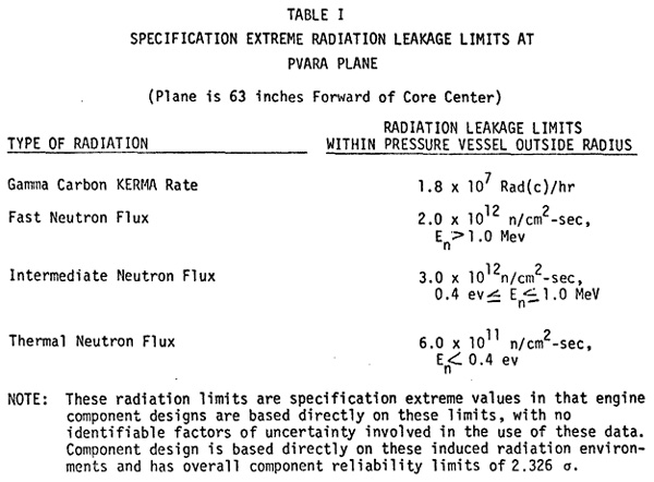
3.1.1.1.11.1 Unmanned Configuration — In the unmanned configuration
(no external shield) the internal shield (internal to the pressure vessel) shall
be no larger than is necessary to prevent radiation damage or heating of engine
components which would preclude meeting their specified performance requirements.
The internal shield shall limit Pressure Vessel and Reactor Assembly (PVARA)
radiation leakage through a plane located at a height of 63 inches forward
of core center, perpendicular to the engine axis, to the levels shown in
Table I, within the radius defined by the pressure vessel outside radius.
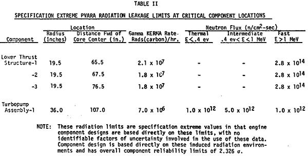
Additionally, the PVARA leakage radiation at critical locations in the engine
system shall be limited to the levels shown in Table II.
Table I
Table II
The internal shield shall be limited to an envelope within the inside radius
of the pressure vessel and an overall thickness not to exceed 18 inches (including
structural and coolant regions).
3.1.1.1.11.2 Manned Configuration — In the manned configuration the
engine shall be capable of providing external shielding which in conjunction
with vehicle and spacecraft shielding reduces the dose per round-trip to 10
rem at the location of each passenger and 3 rem at the location of each flight
crew member in the spacecraft. The manned shield (external shield) shall be
capable of being removed in space for unmanned flight and replaced for manned
flight. Variations in crew shielding attenuation. capability, based on mission
requirements, shall be possible with minimum redesign.
3.1.2.7.3 Nuclear Safety — The engine shall include provisions for
preventing the inadvertent attainment of reactor criticality through any
single or credible multiple failures, malfunctions, or operations during all
ground, launch, flight, and space operations in accordance with the following:
During reactor assembly and for all subsequent shipping,
storage, engine assembly, and handling operations prior to movement to the
launch pad, the reactor shall be provided with a poison wire system such that
the effective neutron multiplication factor shall not exceed 0.95 if the reactor
is flooded with water or liquid hydrogen.
The poison wire system shall remain effective if the reactor
or engine as packaged for shipment is subjected to the Hypothetical Accident
Conditions set forth in Annex 2 of AEC Manual Chapter 0529 Appendix.
The central poison wires alone shall be capable of retaining the
reactor in a subcritical state if all control drums are rotated to their most
reactive position or if the reactor is subjected to a compaction accident.
For ground operations which are conducted with poison wires
removed, as well as for engine use in space flight, protection against
inadvertent criticality shall be provided both by safety measures that prevent
inadvertent roll-out of control drums; and safety measures that prevent valve
operations that could permit LH2 to flow from the propellant tank to the reactor
through either the normal flow path or the cooldown flow path. The safety
measures applied to the PFS valves shall also prevent inadvertent flow of LH2
to the reactor following propellant loading and during launch, boost, and space
operations.
The engine shall provide a means of destruct during launch
and ascent so as to assure sufficient dispersion of the reactor fuel upon
earth impact to prevent nuclear criticality with the fuel fully immersed in
water. The destruct system shall be capable of removal prior to initial reactor
startup in space.
The engine shall include provisions for the safe determination
of sub-critical multiplication when all poison wires have been removed.
The engine shall have a minimum reactivity shutdown margin (no H2 flow, poison wires out, control drums full-in position) of 1.50 at 540°R at all times.
The engine shall include provisions for monitoring the neutron
flux during engine non-operating periods during space flight. The monitor shall
provide an appropriate alarm signal to indicate an abnormal increase in the
neutron level.
6.2 Definitions.
Normal mode — The operation of the engine when all subsystems and components are capable of being operated as designed.
Malfunction Mode
Single Turbopump Operation — The operation of the engine with only one leg of the propellant feed subsystem.
Component Malfunction Mode — The operation of the engine when a component has malfunctioned, other than one which would require single turbopump operation or emergency operation or results in a Category IV failure effect. This mode of operation allows the engine to operate the same as in the normal mode, but without the advantage of the normal mode redundancy.
Emergency Mode — The operation of the engine at a level to effect
safe crew return or to prevent danger to the earth's population subsequent to
a failure effect Category III failure.
Single Failure Point — Any single mode of failure occuring at
the part, component or subsystem level that can be attributed to a specific
internal failure mechanism at the part level and that results in inability of
the engine to meet its normal-mode performance or service life requirements.
System Power Down — Reduction of engine power to a minimum level
consistent with the operating requirements for that particular phase of operation.
Prestart — The phase of an operating mode where all functions of
the engine are performed prior to initiating propellant flow other than that
required for cooling from a previous operation.
Startup — The process of conditioning and bringing the engine
to the first steady state operating point.
Failure Effects
Category I — Failures which produce no significant performance or safety degradation of the system, allow continued operation in the normal mode throughout the rated engine life, and do not result in an increase in the number of Single Failure Points.
Category II— Failures from which the engine can recover and still meet its normal mode performance and service life requirements by switching to or reverting to a recovery mode, but which do result in an increase in the number of Single Failure Points. Failures in this category are further subdivided as follows:
IIA — Failures which degrade the safety of continued operations but which do not produce transient effects and, at the time of failure, do not require automatic or manual action for the recovery mode. Failures of safety systems and standby-redundant components fall within this category.
IIB — Failures which are compensated for automatically by the normal control mode or which produce transient effects which can be tolerated by the system and which permit time for human judgement to be exercised on the method and desirability of the recovery mode. Failures which require the functioning of safety systems or redundant components to preclude Category IIIB effects fall within this category.
IIC — Failures which require immediate malfunction detection and subsequent action to remove or lessen the transient effect and to preclude system damage. Switching to the recovery mode is usually accomplished automatically by the malfunction detection system or by the engine control system. Failures which require the automatic functioning of safety systems or redundant components to preclude Category IV effects fall within this category.
Category III — Failures which result in inability of the engine to meet its normal-mode performance and service-life requirements but which allow Emergency Mode Operation or Single Turbopump Operation. Failures in this category are further subdivided as follows:
IIIA — Failures which require Single Turbopump Operation.
IIIB — Failures which require Emergency Mode Operation.
Category IV — Failures which result in direct injury to the crew, endanger the earth's population, or damage the spacecraft or other stage modules upon which crew survival depends, and/or which preclude Emergency Mode Operation. This category includes failures which produce one or more of the following system effects:
Uncorrectable thrust vector misalignment.
Loss of thrust to less than that required to effect Emergency Mode Operation.
Inability to reduce thrust or unsuccessful shutdown and/or cooldown which precludes engine restart.
Unsuccessful startup to attain thrust equal to or greater than that required for Emergency Mode Operation.
Kerma — A term used to describe the energy deposited by radiation. It is an acronym for Kinetic Energy Released in Material. In this document it is used to describe the intensity of gamma radiation.
I have not managed to find details about shutting down an open-cycle gas core fission engine. But there is an alarming possibility that the only way to shut it down is to eject the entire mass of fissioning uranium out the tailpipe. Not only would this be incredibly radioactive, but also a waste of expensive enriched uranium (cost of $100,000 in 1965 dollars, about $778,000 in 2017 dollars).
START-UP
Startup Sequence
Fill hydrogen ducts and neon system from storage to a pressure equal to approximately 20 atmospheres
turn on neon recirculation pump
inject fuel until critical mass is reached
increase power level and adjust flow rates and cavity pressure to maintain criticality and limit component temperatures to tolerable level
inject propellant seeds when 10 percent of full power is reached
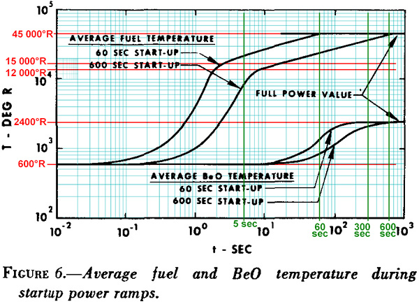
The paper looks at two "power ramps", going from cold to full power in 60 seconds or a more leisurely 600 seconds. Below a temperature of 15,000°R the fusing uranium is heating
up the hydrogen propellant mainly by convection. Above 15,000°R the uranium heats the propellant by infrared thermal radiation.
Since convection does such a pathetic job of transfering heat, most of the fission energy goes to heating up the uranium dust instead of the propellant. In about five seconds flat the uranium reaches 12,000°R, and vaporizes from dust into red-hot gas. Then at 15,000°R thermal radiation takes over and the uranium temperature rises more slowly (which you can see by the way the curve starts flattening out). At 60 or 600 seconds (depending upon which power ramp you used) the uranium is at the nominal temperature of 45,000°R. It won't rise any higher unless the engine is exploding or something rude like that.
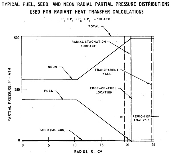
As previously mentioned the hydrogen propellant is pretty much transparent to thermal radiation, which is most unhelpful. Normally the infrared will shoot right through the hydrogen without heating it up. So tungsten dust is seeded into the propellant to soak up the thermal radiation and heat the propellant by conduction. Any thermal radiation that misses the seeding will hit the far wall of the propellant chamber, which is also the beryllium oxide moderator (BeO) helping to keep the uranium fissioning. The thermal heating of the BeO is nothing but wasted energy but the seeding is doing the best it can. The BeO is designed so it can handle up to 2,400°R.
Since the BeO moderator outweighs the uranium dust by several orders of magnitudue, it takes far longer to heat up. As you can see from the graph the uranium fuel starts heating up after only 0.03 seconds but the BeO doesn't even start heating until 10 seconds, about 300 times longer. The uranium gets up to nominal temperature in 60 seconds but the BeO takes 300 seconds. And the BeO only gets up to 2,400°R while the uranium is smokin' at 45,000°R. That is for the 60 second ramp. The 600 second ramp has both the uranium and BeO all warmed up at the same time, only because 600 seconds gives the BeO time to catch up.
However, the shorter 60 second ramp is desireable, because the 600 second ramp wastes precious propellant. Take the propellant mass required for a standard 20 minute burn at full power. The 60 sec ramp requires an additional 2.7% propellant as startup wastage. The 600 sec ramp requires a whopping 27% additional, which is totally unacceptable. What, do I look like I am made of propellant? The paper says it might be possible to reduce the ramp time down to 6 seconds, in the interest of reducing the propellant startup wastage even further (presumably to 0.27%).
The critical mass of uranium-235 fuel required in the quartz tubes increases during the ramp up. It requires 18.6 pounds at zero power up to 30.9 lbs at full power. For the 60 second ramp up full power initially happens at 28.2 lbs, but rises to 30.9 lbs at 300 seconds. This is because at 60 seconds the BeO moderator has only warmed up about two-thirds of the way to its max temperature. Apparently once the BeO is fully warmed up the critical mass rises.
When the paper was read, one of the attendees was skeptical about pressure. Specifically if the pressure of the uranium/neon mix is not the exact same as the pressure of the hydrogen propellant, the pressure differential will shatter the quartz tube like dropping an old-school incandescent lightbulb on a concrete floor. The paper authors insisted that the two pressures could be balanced rapidly enough to prevent that unhappy state of affairs. They say that a differential of two or three atmospheres will shatter the blasted tube, so they want to keep the diff under 2/3rds atm. Yikes, I didn't know that! That would instantly ruin the propulsion system, and spray everybody and everything close by with fissioning uranium.
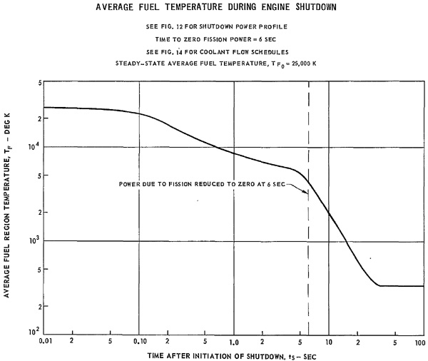
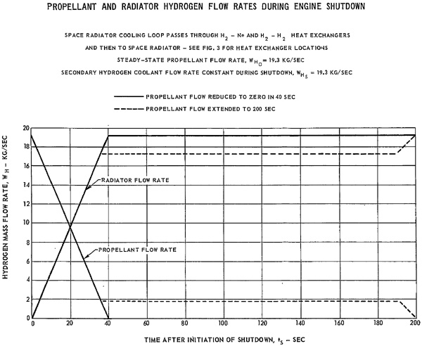
Close Fuel Injection Control Valve (turn off the uranium)
Begin Linear Decrease in Propellant Flow Rate (propellant flow past light bulbs to exhaust nozzles)
Begin Linear Increase in Radiator Flow Rate (flow from coolant heat exchanger to radiator)
Maintain Secondary Circuit (flow of hydrogen coolant) and Cavity Neon Flow (buffer gas flow inside the quartz light bulbs) at Full Power Value.
Once the engine shut-down sequence is initiated, it takes six seconds for the power level to drop to zero. It only takes 0.8 seconds for power level to drop to 0.01 of full power, during which time the contained uranium fuel drops from the steady-state level of 13.65 kg down to 11.5 kg.
Gimbals are one technique of thrust vectoring, allowing the thrust to go off center. The pilot uses this to yaw and pitch. If there are multiple engines with enough separation from the spacecraft's axis, gimbaling can be used roll as well.
It can also be used in emergencies if during thrust the rocket "falls off its tail." That is, if the center of gravity unexpectedly shifts, and the engines can gimbal by enough degrees off center, they can compensate.
In a 1969 US Atomic Energy Commission pamphlet on NERVA, it had this to say:
A critical structural problem arises at the junction between the engine and rocket body, however. Across this junction must be transmitted the entire engine thrust that is conveyed upwards from the nozzle through the engine exoskeleton. Ordinarily, such a joint would present no engineering difficulties. But in this case, the joint must be flexible. All big rockets have their engines mounted on gimbals that permit the "driver" to steer them.
Gimballing chemical engines is relatively easy because they are lightweight. But, in a nuclear rocket, the heavy reactor replace the empty combustion chamber of the chemical rocket. Despite the added weight, suitable flexible joints now have been designed.
Dr. Crouch is unsure about this. He notes that unlike a chemical rocket, the poor gimbal is trying to swing an entire reactor so the actuation loads will be large. Even worse: the gimbal is subject to cryogenic temperatures, nuclear radiation, and thrust loads. Simultaneously. He is of the opinion that a more optimal solution would be secondary injection, jetavators, or a movable nozzle.
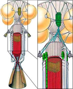
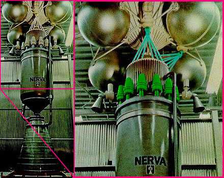
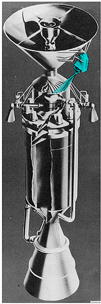
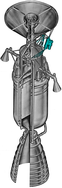
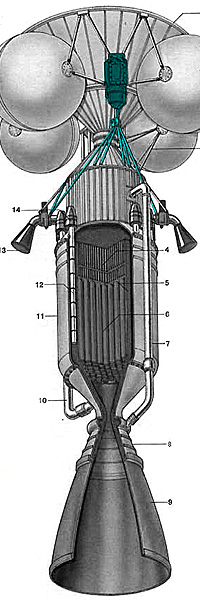
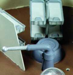
Having said that, here are the gimbals designed for the NERVA project.
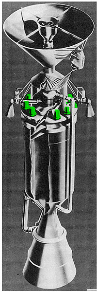
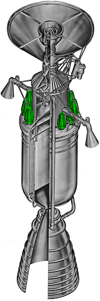
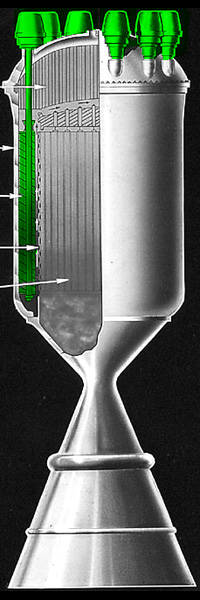
Control drums and actuators in green, gimbals in blue.
Control drums and actuators in green, gimbals in blue.
In the images here, the gimbals are the network of blue rods emerging from the bottom of a hydraulic piston. The wasp-waist in the center is the pivot. The green "mushroom caps" are the control-drum actuators, perched on top of the control drums protruding from the reactor.
Note that the gimbals are a nasty trouble spot. If one jams, that engine cannot be steered. The proximity to the dangerously radioactive engine makes repair difficult. This is a good place for a waldo.
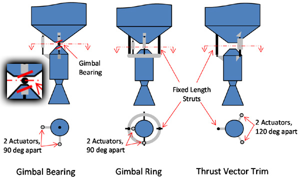
THRUST VECTOR CONTROL
Figure 1
Control of these large vehicles during powered flight is expected to use some means of thrust vector
control, TVC. Thrust vector control allows the alignment of the vehicle thrust with vehicle center of
gravity (CG) to maintain straight line flight or to induce vehicle steering as desired. The objective of this
paper is to define the requirements and conceptual design of thrust vector control systems for NTR
applications. Several different vehicles will be examined to explore vehicle and mission influences on
TVC design.
A reaction control system (RCS) can also manage vehicle attitude, and is essential during times when
engines are not thrusting. While the NTR engines are thrusting, the use of thrust vector control can avoid
most use of RCS propellant. Otherwise, RCS propellant consumption could become excessive in some
cases, especially off-nominal situations such as thrust asymmetry due to engine malfunction. In a multiengine
vehicle, differential engine thrusting could be used to steer the vehicle, as an alternative to TVC.
But this method would not work if one of three engines failed. Definition of the capabilities of a TVC
system also helps define the requirements of the RCS.
Gimbaling of engines is the most common method of thrust vector control for large rockets.
Gimbal Bearing
Typical
configurations includes a gimbal bearing attached to the engine that allows two axis rotation of the engine
(e.g., yaw and pitch rotation) but prevents rotation about the axis of the engine. The gimbal bearing
carries most of the engine thrust load.
Gimbal Ring
Two actuators, attached to the engine and vehicle structure can be
mounted 90° apart to provide full two-axis gimbaling. Instead of a gimbal bearing on the engine axis,
gimbal motion can be achieved by the use of a gimbal ring that is external to the engine, as in a gyroscope
mount. One gimbal actuator would be attached to the ring, the other attaches to the engine, 90° apart.
Thrust Vector Trim
An alternative method of engine steering was considered during the Nuclear Engine for Rocket
Vehicle Application (NERVA) program (Ref. 4). This method, designated Thrust Vector Trim (TVT)
uses one engine attach point with a fixed ball and socket joint and two moveable engine attach points that
translate parallel to the rocket engine axis. The fixed and moveable points are located 120° around the
engine axis. By actuating the moveable points fore and aft, the engine thrust axis can be directed within a
cone of operation. The advantage of this configuration is the elimination of the engine gimbal bearing;
there is only the need for a flexible connection to carry propellant into the engine. The disadvantage of
this configuration is that the mechanisms that provide the engine movement must each continuously carry
about one third of the engine thrust load. The engine attach points must similarly be designed to react the
same thrust loads. This method may be attractive for relatively low thrust engines. Mechanical engine
steering concepts are shown in Figure 1.
Other thrust vector control methods include the use of paddles or vanes to alter the rocket engine
exhaust to direct the net thrust vector. These methods are problematic because the thrust directing
elements must withstand the high temperatures in the rocket exhaust.
The countdown was still at ten seconds when we were startled by a blast of light. For a moment, we wondered if Olympus had also met with catastrophe. Then we realized that someone was filming the take-off, and the external floodlights had been switched on.
During those last few seconds, I think we all forgot our own predicament; we were up there aboard Olympus, willing the thrust to build up smoothly and lift the ship out of the tiny gravitational field of Phobos, and then away from Mars for the long fall sunward. We heard Commander Richmond say "Ignition," there was a brief burst of interference, and the patch of light began to move in the field of the telescope.
That was all. There was no blazing column of fire, because, of course, there's really no ignition when a nuclear rocket lights up. "Lights up" indeed! That's another hangover from the old chemical technology. But a hot hydrogen blast is completely invisible; it seems a pity that we'll never again see anything so spectacular as a Saturn or a Korolov blast-off.
From "Transit of Earth" by Arthur C. Clarke (1971)
Power
The Power Plant will probably be some species of space nuclear reactor. Clever designers will use the Bimodal NTR concept to get double duty from a single reactor.
BATTLESHORT
Battleshort (sometimes "battle short") is a condition in which some military equipment can be placed so it does not shut down when circumstances would be damaging to the equipment or personnel. The origin of the term is to bridge or "short" the fuses of an electrical apparatus before entering combat, so that the fuse blowing will not stop the equipment from operating.
According to Allied Ordnance Publication AOP-38-3, a NATO publication, a battleshort is "The capability to bypass certain safety features in a system to ensure completion of the mission without interruption due to the safety feature." It also says, "Examples of bypassed safety features are circuit overload protection, and protection against overheating".
In peaceful situations one would want equipment to shut down so it is not damaged. In a battle or emergency, where the survival of the vessel (or other protected asset) is dependent upon the continued operation of the equipment, it is sometimes wiser to risk equipment damage than have the equipment shut down when it is needed. For example, the electrical drives to elevate and traverse the guns of a combat warship may have "battleshort" fuses, which are simply copper bars of the correct size to fit the fuse holders, as failure to return fire in a combat situation is a greater threat to the ship and crew than damaging or overheating the electrical motors.
Battleshorts have been used in some non-combat situations as well, including the Firing Room/Mission Control spaces at NASA during the manned Apollo missions — specifically the Moon landings.
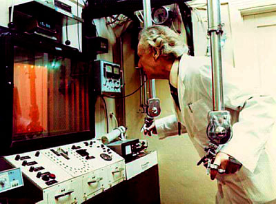
The various controls, tongs, and remote control "waldoes" will reach around or penetrate the anti-radiation shadow shield, and there may be auxiliary lead baffles. Peeking around the baffles is how Rhysling lost his sight in Heinlein's "The Green Hills of Earth".
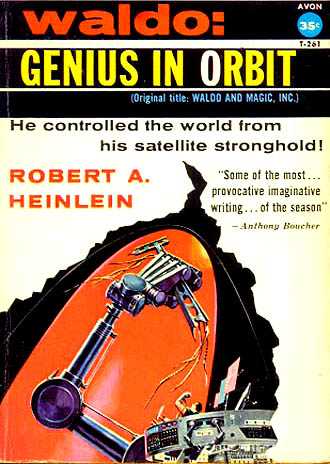
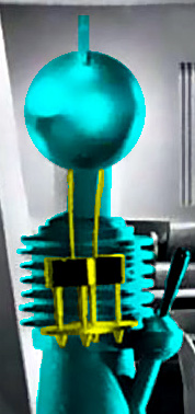
Waldo by Robert A. Heinlein, 1940. This is where the term originated.
The various controls, tongs, and remote control "waldoes" will reach around or penetrate the anti-radiation shadow shield, and there may be auxiliary lead baffles. Peeking around the baffles is how Rhysling lost his sight in Heinlein's "The Green Hills of Earth".
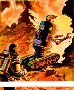
Robots
Galaxy magazine, July 1952
Remember that the shadow shield will be in the floor, with the engine below that. Closed-circuit TV monitor will help Astro see what he is doing, but if they are damaged, he'll have to make do with mirrors and/or doing it by touch. What he really needs is one of Tom Swift Jr.'s Giant Robots, which were designed to do maintenance inside nuclear power plants. There is more about robots here.
For external repairs, the chief engineer might use something similar to the amazing Canadarm 2, which is currently on active duty on the International Space Station. Unlike the first Canadarm, this one is not attached at either end. Instead, either end can plug into special sockets ("power data grapple fixtures") built at strategic spots on the surface of the station. Canadarm 2 can literally walk on the surface of the station to where it is needed, moving end-over-end like a giant metal inch worm. The main limitation is that each "step" must end at a socket, but this is due to power and control signal issues. A more advanced version might be self contained enough to not require sockets, just hand-holds or other protrusions that it could grab.
Canadarm 2 is quite large, 17.6 meters (57.7 feet) long when fully extended. It can move payloads with a mass up to 116 metric tons.
On your atomic rocket, one would use arm(s) long enough to reach any spot on the radioactive engine.
REPAIR ACCESS
You'll need locations on access ports, but chances are they'll be basically compressed — when crews do major overhauls they will pull it apart structurally (which is much simpler in space). While under power there won't be anywhere to go inside a fuel system or reactor. It will be much like a car or tank — there's nowhere you can 'get to' inside of it. There is no 'inside' that is large enough for a human being. The same is true of much of a submarine. You can get to the face plate of the reactor, but if you have trouble inside the reactor you dock. It's simply not practical to build hallways into a vessel for which mass and volume are at such a premium. You might have internalized robot tools, but no human spaces. In fact almost everything will be robot or computerized. People are too slow and soft to be of much use for most purposes in space. There isn't enough time between detecting a micrometorite to let Chekov make a decision — it shows up, it gets blasted, all automatic. Anything else would be suicide.
For this reason (and the sheer cost of training, getting a human to space and supporting them as well as the mass and volume these systems take up) almost everything — from mining to combat — will be computerized. If there is a human in the loop it will be as a drone pilot a light second away in a specialized control vehicle, not a crewman. Humans can not think, move or even see fast enough to be useful at multiple miles a second interactions. And if you have real AI almost everything in a space operation will be run by AI. People who refuse to for moral qualms or whatever will simply lose out compared to those who don't have such scruples and be replaced by them. Even a fully cyborgized human is still too fragile compared to a rad-shielded super computer which can replace all that water, air and other useless junk with duranium plates. So far almost everything useful that's ever been done in space has been done by automated and remote controlled machines. This is likely to become more prevalent in the future, not less. It is much easier to weld radiation shielding onto a robot than onto a man. Robots take isolation and 5G acceleration much better than bags of water. Presently the main role humans have is operational. This is true not just in space but on the ground and in the water — fire control for point defense is entirely automated, not just the individual ships but the whole task group is link-fired by the same dumb computer. The human's role is to flip the switch and turn it on. Likewise for aircraft — aircraft are flown almost entirely by autopilots. Humans just watch for obvious errors and because of regulations. A jet fighter pilot doesn't aim his guns or fire his missiles — his computer does. He just turns the damn thing on and off and picks a direction to go in. Human agency is almost entirely confined to strategic decision making, not function. If you have true AI then they'll probably fail at that, too. If you want a situation where characters make a bunch of decisions in a realistic futuristic environment you should probably make them military commanders, billionaires or robots; because those are the people who actually get leeway in operational procedure.
So if you are doing in-ship reactor repairs it won't be Scotty climbing down a tunnel. It will be a snake-like robot arm with 10 thumbs and a laser attached controlled by a guy sitting at CON with a joystick. If that can't handle it then you need to dock, or at least go EVA in a WALDO so you can start pulling the whole thing apart like Legos. Ships generally do not make allotment for doing things incorrectly, so they will not have spaces for men to fit in radioactive death chambers. It will be wall-to-wall radioactive death machinery.
Cutting tools include knives, chisels, lathes, saws, planers, and sanders. Also included under cutting tools are CNC milling machines and Laser Cutters.
Joining tools include hammer and nails, screwdriver and screws, soldering gun and solder, socket wrench and bolts, arc welders, and glue. Also included under joining tools is solid freeform fabrication for rapid prototyping.
Since every gram counts, instead of carrying tons of spare parts that may never be needed the ship might carry bar stock for spares to be created as needed. Or input material for the 3D printer. Yes, the 10-meter Orion Drive spacecraft carries 1.13 metric tons of spares, 2.27 metric tons of repair equipment, and half a metric ton of checkout instrumentation; but that monster just doesn't even notice a few extra hundred tons of payload.
Rather than carry many extra tons of spare parts, which might or might not be used, the ship is equipped with extensive workshops to repair or manufacture the required parts as they become needed by the maintenance crews. Each workshop features a large number of automated machine tools and precision autofacs that hold the specifications of all parts in memory. Only the most sensitive and specialized parts, such as the microscopic computer nodes and chips, are held in storage.
The microgravity stations are sealed transparent bays with built-in gloves. Items to be repaired are slipped inside through a zippered opening, and can then be disassembled without fear of small parts flying off. Tools can also be left floating free inside the enclosure rather than having to be tethered. Machine tools are housed within similar enclosed bays for safety and tidiness reasons; articulated arms hold the part while it is being machined.
(ed note: I will observe that enclosures make sense from the standpoint of eye safety. You do NOT want to have a free-floating metal shaving getting into your eye. However, it is not a good idea to have one's tools untethered if unexpected spacecraft accelerations can occur.)
Are the supplies about in—we leave in an hour.” “Yes,” grumbled the engineer. “Look at it—twelve hundred feet long. Half a million tons. We get our power by transpon beams tapping any sun, so we carry no fuel. We drive it with momentum waves, and don’t have to carry rocket discharge mass. We rectify the air, and use it time after time; we recover water, so we need no great water supplies. And still—I can’t carry a decent supply of spares. And I’ll need ‘em. Look at the gang of theorists I’ve got to work with! Astronomers I’ll have to rely on for navigators. Physics research scholars for electricians. Chemical geniuses for rectification technics. Two laboratory mechanicians for repair technics. Watch that crew wreck stuff—and no spares to replace them with. Great spaces—and we plan to go as much as 25,000 light-years from home!”…
…“I know-I know,” groaned the engineer. “But they might have given us more real spacers, and fewer theorists.”
Silently Thi Athron nodded, and went back to the power room. Tha Yory was working over the small lathes on one side of the room, with a laboratory mechanician, and with much cursing.
“You imbecile—you sub-normal idiot! Can’t you see that is a reverse pattern? Can’t you remember that what is a projection here is to be a countersink in the metal? Ahrrrr—teach me—teach me how to work that machine that I may teach you your craft. Must I not only make the patterns, but make the metals too?” Tha Yory stopped as Zhi Athron appeared smiling. “He finds the work more difficult, Tha Yory, because he is used to working from pattern-drawings.” “But the blundering error of Nature can’t cut from pattern, and I can’t draw plans, and neither can any one else around so far as I can see.” “What part is it? Have we had so many breakdowns as to exhaust the spare parts list?” “No,” replied Tha Yory, “but like any good engineer when I have a crew that doesn’t yet know the difference between the theoretical limits and the factor of safety, I intend to keep up my storeroom—such as it is. I’m working on some other spares, too, some that were too big to carry, when we started, but can now be carried in the exhausted store rooms.” “Ah, then that is why you swept in those tons of meteoric material when we stopped at that star back there,” Thi Athron nodded. “What in particular are you aiming at?” “Spare high-speed apparatus. We have only five different parts for that—and if we had an accident that smashed it, and the machine shop too, we’d be lost forever. If it happened between stars, unless we have a supply of metal a lot bigger than we have, we’d never return to home.
The machinery, decks, and walls will have lots of access panels to allow the engineers to make repairs. If the machinery is large, there will be ladders and catwalks. The lighting will also be bright and harsh. The walls will have tool bays, spare parts lockers, fire control gear, and similar items.
The engineering deck is likely to be a noisy place, with all the heavy machinery. Engineers might need ear-plugs, and good lip-reading skills. If the situation is more high-tech, they will wear combination radio/hearing protection headsets.
The engineer has a logbook as well.
If some of the spares are larger than, say, a person, either the corridors or the airlock will have to be large enough to accommodate it.
Another thing you might want to think about, based on my naval engineering days: how big are the biggest parts in the engineering spaces? That is, what's the size of the biggest thing you might have to move in and out of the craft for repairs or replacement? The radiators are already on the outside. Are there reactor vessels, fusion containment cells, or some other nifty big bits that cannot be broken down into smaller parts? How about tanks (for algae, fuel, water, sewage, recycling, air)? You're going to need a way to get that stuff on and off, and a way to handle the large mass safely.
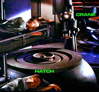
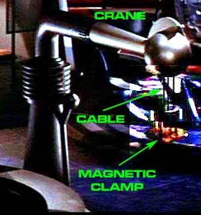
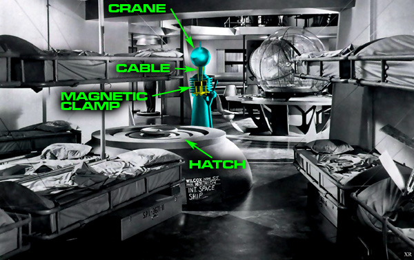
In the movie Forbidden Planet, there is a small crane mounted over a deck hatch to facilitate moving equipment between decks. It is shown in the scene where the invisible monster enters through the hatch into the bunkroom full of sleeping enlisted men. It is the long metal arm that the invisible monster bumps out of the way.


"Kung," Griffin asked over coffee next afternoon, "how well up are you on Chinese mythology?"